
High flatness integrated solar power integral roof and rapid integration method

A flatness, solar energy technology, applied in the field of solar power generation, can solve problems such as roof water leakage, different photovoltaic module sizes, and photovoltaic modules difficult to adapt to changes in roof area, and achieve the effect of reducing construction costs, good drainage performance, and avoiding hidden dangers of water leakage.

Active Publication Date: 2017-04-12
烟台鼎城新能源光伏有限公司
View PDF7 Cites 0 Cited by
  • Summary
  • Abstract
  • Description
  • Claims
  • Application Information

AI Technical Summary

Problems solved by technology

The method of bracket installation is technically an application method of adhesion, and the method of colloidal gap filling is to use the corresponding structure to pave the photovoltaic square array instead of building (constructing) the roof, but because of the use of colloid to fill the space between photovoltaic modules There is bound to be a hidden danger of roof leakage caused by aging and cracking of the colloid
In addition, the size and form of the roof area of ​​buildings are different, requiring different sizes of photovoltaic modules. Ordinary photovoltaic modules are difficult to adapt to changes in roof area.

Method used


Image

  • High flatness integrated solar power integral roof and rapid integration method
  • High flatness integrated solar power integral roof and rapid integration method
  • High flatness integrated solar power integral roof and rapid integration method

Examples


Embodiment

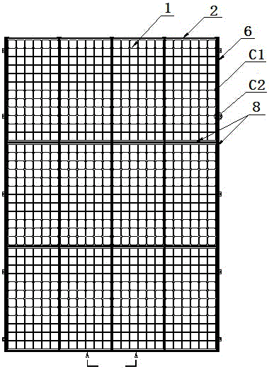
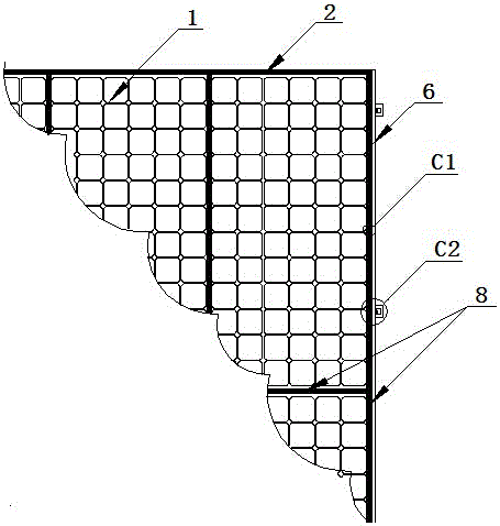
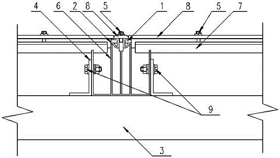
[0029] The high flatness integrated solar power generation integral roof in this embodiment consists of a frameless photovoltaic module 1 and a sealing tape 2 covering the periphery of the frameless photovoltaic module to form a photovoltaic module. The upper and lower ends and the left and right sides of the photovoltaic module are A pressure bar 8 is installed, and a water tank 6 is arranged at the lower part of the connection gap of the adjacent photovoltaic modules. The water tank 6 is erected on the upper surface of the purlin 3. The water tank and the purlin are fixedly connected by the connecting corner code 4 and the bolt 9. The pressure strip on the left and right sides of the photovoltaic module is connected to the water tank 6 are fixedly connected by self-drilling and self-tapping screws 5; the top of the water tank 6 is equipped with a horizontal connecting back strip 7, and the pressure strips at the upper and lower ends of the photovoltaic module and the horizonta...


PUM


Abstract

The invention relates to an integrated high-flatness solar power generation integral roof and a quick integration method and belongs to the technical field of solar power generation. The integrated high-flatness solar power generation integral roof is characterized in that frameless photovoltaic modules and sealing adhesive tape wrapped on the four edges of each frameless photovoltaic module form photovoltaic modules; the upper end, the lower end, the left side and the right side of each photovoltaic module are all provided with pressing bars; a water channel is arranged below a connecting gap between the adjacent photovoltaic modules; the water channels are arranged on the upper surfaces of purlines in an erected mode, and the pressing bars on the left side and the right side of each photovoltaic module are fixedly connected with the corresponding water channel. Transverse connecting backing strips are mounted on the water channels, and the pressing bars at the upper ends and the lower ends of the photovoltaic modules are fixedly connected with the transverse connecting backing strips. The quick integration method comprises the steps that (1) the sealing adhesive tape is wrapped on the frameless photovoltaic modules; (2) the water channels are fixedly mounted on the upper surfaces of the purlines, and the transverse connecting backing strips are mounted on the water channels; (3) the photovoltaic modules are laid; (4) the photovoltaic modules are fixed. By the adoption of the integrated high-flatness solar power generation integral roof, the hidden danger of water leakage is avoided; by the adoption of the quick integration technology, the photovoltaic module frame packaging process is omitted, materials for packaging are saved, and the working efficiency is improved.

Description

technical field [0001] The invention relates to a high flatness integrated solar power generation integral roof and a rapid integration method, belonging to the technical field of solar power generation. Background technique [0002] Solar power generation is known as the most ideal new energy. With the country's emphasis on distributed solar power generation applications, there are more and more applications of photovoltaic building integration. At present, the solar power generation applied to the roof is mainly installed with brackets or colloidal caulking. The method of bracket installation is technically an application method of attachment, and the method of colloid caulking is to use the corresponding structure to pave the photovoltaic square array instead of building (construction) roof, but because it uses colloid to fill the gap between photovoltaic modules There is bound to be a hidden danger of roof leakage caused by colloid aging and cracking. In addition, the ...

Claims


Application Information

Patent Timeline
Patent Type & Authority Patents(China)
IPC IPC(8): E04D13/18H02S20/25
CPCY02B10/10Y02E10/50
Inventor 余国光
Owner 烟台鼎城新能源光伏有限公司
Learn More