Pressure limiting type liquid column separation preventing air valve

A column separation and air valve technology, applied in the direction of balance valve, valve device, safety valve, etc., can solve the problems of increasing water pressure in the pipe, high water pressure of high-pressure gas in the pipeline, and inability to discharge quickly, so as to prevent water hammer when starting the pump. , The effect of reducing the pressure in the pipe and preventing the pipe from bursting

Inactive Publication Date: 2015-02-25
WUHAN UNIV
View PDF5 Cites 11 Cited by
  • Summary
  • Abstract
  • Description
  • Claims
  • Application Information

AI Technical Summary

Problems solved by technology

When the power supply of the pump station unit is suddenly cut off or the pump is shut down due to an accident, it quickly replenishes a large amount of air into the pipeline to eliminate the vaporization phenomenon caused by the separation of the liquid column; By slowly exhausting, it acts as a buffer to prevent bridging water hammer; however, during the pump start process, this type of air valve cannot quickly discharge the gas in the pipe to prevent the occurrence of pump water hammer; In the process, as the water supply distance becomes longer and the flow rate continues to increase, the ordinary air valve often causes t

Method used


Image

  • Pressure limiting type liquid column separation preventing air valve
  • Pressure limiting type liquid column separation preventing air valve
  • Pressure limiting type liquid column separation preventing air valve

Examples


Example Embodiment

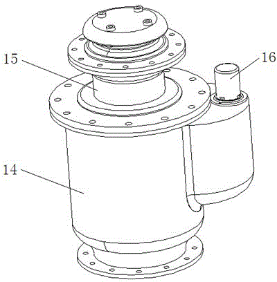
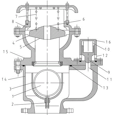
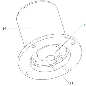
[0017] The present invention will be further explained below in conjunction with the drawings: Figure 1-4 As shown, a pressure-limiting anti-liquid column separation air valve includes a metal ball 1 that can move up and down by liquid buoyancy in the lower chamber, and the metal ball is controlled by controlling the movement of a shaft 2 connected to the lower end of the metal ball 1 The guide plate 3 in the moving direction has a large-diameter air inlet channel above the metal ball 1; the support plate 4 in the upper chamber supports the floating plate 5, wherein the center of the floating plate 5 is provided with an exhaust hole 6, which There is a pressure limiting spring 7 and a limiting valve body 8 on the upper side; a conical valve head 9 is provided on one side of the drain chamber, a pressure limiting spring 10 is provided on the upper side of the conical valve head 9 and a flow hole 11 is provided below, and a drain chamber The valve body is provided with an annula...


PUM


Abstract

The invention discloses a pressure limiting type liquid column separation preventing air valve. According to the pressure limiting type liquid column separation preventing air valve, an upper cavity (15) and a lower cavity (14) are connected through a flange, and the lower cavity (14) is further communicated with a pressure relief chamber (16); an air inlet and outlet channel is formed in the lower portion of the upper cavity (15), a floating plate (5) is connected with the top of the upper cavity (15) through limiting springs (7), and a supporting plate (4) used for supporting the floating plate (5) is arranged at the top end of the air inlet and outlet channel; an air inlet and outlet channel is formed in the upper cavity (15), a guide plate (3) with a U-shaped section is arranged in the air inlet and outlet channel, a metal ball (1) is arranged in the guide plate (3), a shaft lever (2) is arranged in the center of the bottom of the metal ball (1), and the lower end of the shaft lever (2) is a free end. The pressure limiting type liquid column separation preventing air valve has the advantages that the pressure limiting type liquid column separation preventing air valve is installed along a water supply pipeline, efficiency can be improved, and a pump starting water hammer can be avoided; when an accident occurs and a pump stops, by means of the adjustment of the floating plate, when negative pressure appears in the pipeline, the vaporization phenomenon can be avoided by absorbing a large amount of air; when the pressure in the pipeline is too high, a buffering function is achieved through micro air exhaust, a closing water hammer is avoided, and part of high-pressure water in the pipeline can be drained through the pressure limiting type liquid column separation preventing air valve to lower pressure.

Description

technical field [0001] The invention relates to the technical field of air valves, in particular to an air valve which can reduce the pressure inside a pipe by releasing part of high-pressure water. Background technique [0002] Air valve is the most commonly used water hammer protection measure in water supply engineering. At present, in the water supply system, air valves are often arranged along the pipeline, especially at local convex points. When the power supply of the pump station unit is suddenly cut off or the pump is shut down due to an accident, it quickly replenishes a large amount of air into the pipeline to eliminate the vaporization phenomenon caused by the separation of the liquid column; By slowly exhausting, it acts as a buffer to prevent bridging water hammer; however, during the pump start process, this type of air valve cannot quickly discharge the gas in the pipe to prevent the occurrence of pump water hammer; In the process, as the water supply dista...

Claims


Application Information

Patent Timeline
IPC IPC(8): F16L55/07F16L55/045F16K17/04
CPCF16L55/055F16K17/0406F16L55/07
Inventor 蒋劲陈昶翁晓红肖志怀李东东宋红岩
Owner WUHAN UNIV
Why Eureka
Try Eureka