
Lens group and light source device using same

A lens group and lens technology, applied in the direction of lens, light source, electric light source, etc., can solve the problems of not being able to completely eliminate the bright spots of the light field and reduce the overall light output effect, and achieve the effects of uniform light field distribution, energy reduction, and elimination of bright spots

Inactive Publication Date: 2015-02-25
HONG FU JIN PRECISION IND (SHENZHEN) CO LTD +1
View PDF7 Cites 0 Cited by
  • Summary
  • Abstract
  • Description
  • Claims
  • Application Information

AI Technical Summary

Problems solved by technology

[0003] However, in actual use, after the light emitted by the LED light source is diffused by the lens, because the light is relatively concentrated near the optical axis of the LED light source, it cannot completely eliminate the hot spot in the center of the light field. When it is used in backlighting will reduce the overall light effect

Method used


Image

  • Lens group and light source device using same
  • Lens group and light source device using same
  • Lens group and light source device using same

Examples


Embodiment Construction

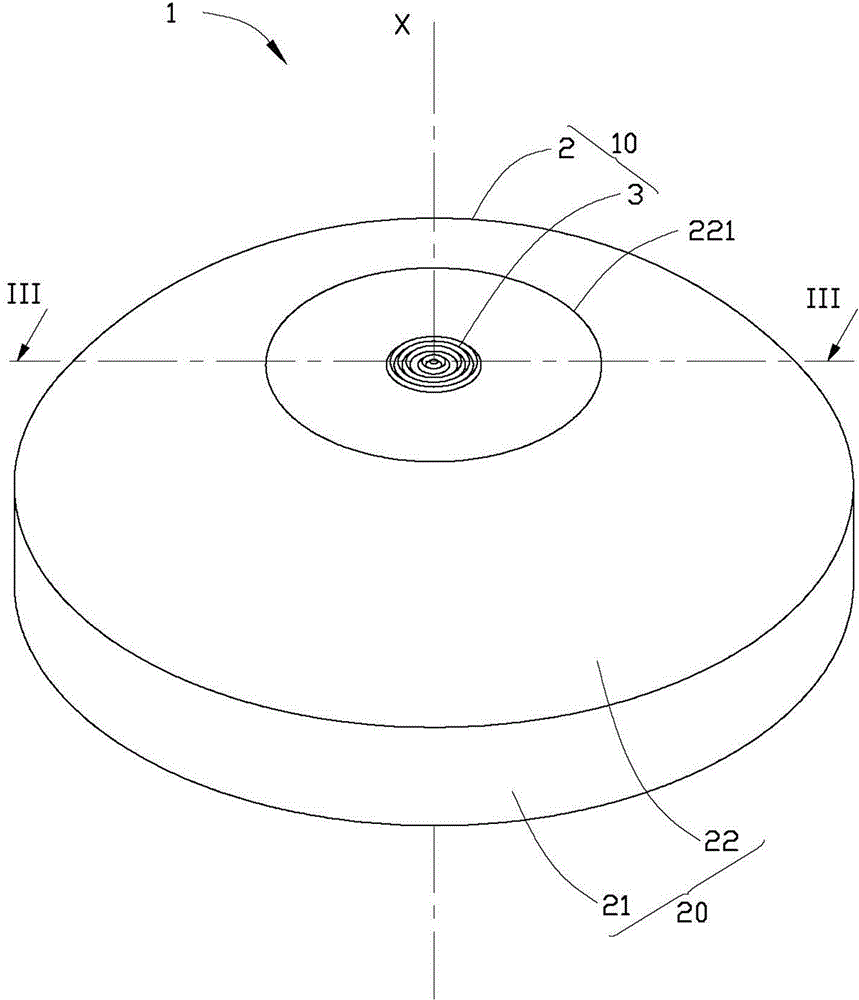
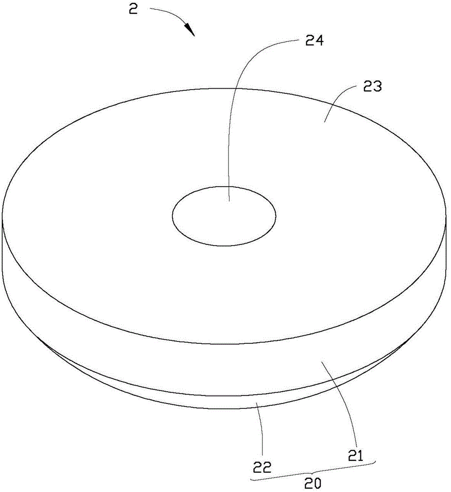
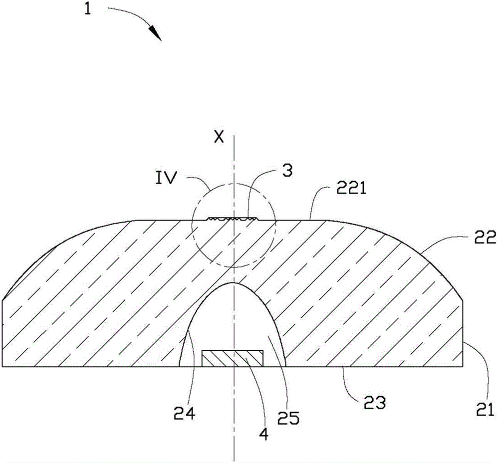
[0018] see Figure 1 to Figure 3 , the light source device 1 of the first embodiment of the present invention includes an LED light source 4 and a lens group 10 matched with the LED light source 4 . The lens group 10 includes a lens 2 and a micro-lens group 3 on top of the lens 2 . The microlens group 3 includes a plurality of ring-shaped microlens units 31 , and these ring-shaped microlens units 31 are arranged on the top of the lens 2 in circles from inside to outside. Among the light emitted by the LED light source 4 , the light near the optical axis enters the lens 2 and is scattered out of the lens group 10 through the micro-lens group 3 on the top of the lens 2 .

[0019] The lens 2 includes a light incident surface 24 and a light exit surface 20 opposite to the light incident surface 24 . The lens 2 has a central axis X passing through the lens 2 . The light incident surface 24 of the lens 2 is symmetrical to the central axis X of the lens 2 , and the light outgoing ...


PUM


Abstract

A lens group comprises a lens and a micro lens group matched with the lens. The lens comprises a light incoming face and a light outgoing face opposite to the light incoming face. The lens is provided with a central shaft. The light incoming face and the light outgoing face of the lens are respectively symmetrical relative to the central shaft. The micro lens group is arranged on the light outgoing face of the lens. The micro lens group comprises a plurality of annular micro lens units which are arranged on the light outgoing face of the lens in a circle by circle manner. Each annular micro lens unit comprises a first scattering face and a second scattering face connecting with the first scattering face. The first scattering face and the second scattering face of each annular micro lens unit are inclined relative to the central shaft of the lens. The lens group has the advantages that the micro lens group is disposed on the light outgoing face of the lens, light of areas near the optical axis of an LED light source is scattered out of the lens group by the micro lens units and is transmitted in various directions, optical field central area energy is lowered, and optical field central bright spots are eliminated. The invention further relates to a light source device using the lens group.

Description

technical field [0001] The invention relates to a lens group and a light source device using the lens group. Background technique [0002] Light emitting diode (light emitting diode, LED), as an efficient light source, has many characteristics such as environmental protection, power saving, and long life, and has been widely used in various fields, especially the field of backlighting. In the field of backlighting, in order to uniform the light, the LED light source is usually used with a diffusion lens, so that the light of the LED light source can be emitted at a larger angle, so as to achieve the effect of large-area lighting. [0003] However, in actual use, after the light emitted by the LED light source is diffused by the lens, because the light is relatively concentrated near the optical axis of the LED light source, it cannot completely eliminate the hot spot in the center of the light field. When it is used in backlighting will reduce the overall lighting effect. ...

Claims


Application Information

Patent Timeline
Patent Type & Authority Applications(China)
IPC IPC(8): F21V5/04G02B3/00F21S2/00F21Y101/02
CPCF21V5/048F21S2/00
Inventor 王何立颖洪毅
Owner HONG FU JIN PRECISION IND (SHENZHEN) CO LTD
Learn More