
ct system and its method

A CT image, motion direction technology, applied in image enhancement, instrument, material analysis using wave/particle radiation, etc., can solve the problems of increased labor and time cost, multiple scanning time, high maintenance cost, and improve the recognition accuracy. , the effect of speeding up the scanning process and good image quality

Active Publication Date: 2017-06-16
TSINGHUA UNIV +1
View PDF10 Cites 0 Cited by
  • Summary
  • Abstract
  • Description
  • Claims
  • Application Information

AI Technical Summary

Problems solved by technology

The first is the problem of scanning speed. Faster inspection speed can help relieve the pressure brought by passenger flow and cargo flow, and fast scanning usually requires a higher speed slip ring. Due to processing accuracy and reliability issues, the cost of high-speed slip rings is very high. Expensive, high maintenance costs, difficult to promote
The second is the problem of false positives and false negatives. The automatic identification and alarm function of CT technology is difficult to achieve 100% accuracy. The inspection of contraband still needs manual assistance to judge, and even open the package for inspection. Usually, it takes several minutes or even more than a dozen for an open package inspection. Minutes, which greatly increases the cost of manpower and time, and seriously restricts the improvement of security inspection efficiency
In order to alleviate this problem, there are currently devices using secondary scanning technology on the market, which can improve the quality of CT images and reduce the number of unpacking inspections by performing secondary high-precision scanning on suspicious bags. There are problems such as taking up more scanning time and interrupting the security check process

Method used


Image

  • ct system and its method
  • ct system and its method
  • ct system and its method

Examples


Embodiment Construction

[0027] Specific embodiments of the present invention will be described in detail below, and it should be noted that the embodiments described here are only for illustration, not for limiting the present invention. In the following description, numerous specific details are set forth in order to provide a thorough understanding of the present invention. It will be apparent, however, to one of ordinary skill in the art that these specific details need not be employed to practice the present invention. In other instances, well-known circuits, materials or methods have not been described in detail in order to avoid obscuring the present invention.

[0028] Throughout this specification, reference to "one embodiment," "an embodiment," "an example," or "an example" means that a particular feature, structure, or characteristic described in connection with the embodiment or example is included in the present invention. In at least one embodiment. Thus, appearances of the phrases "in...


PUM


Abstract

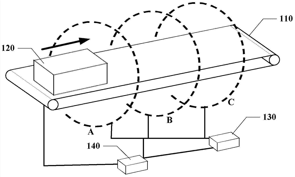
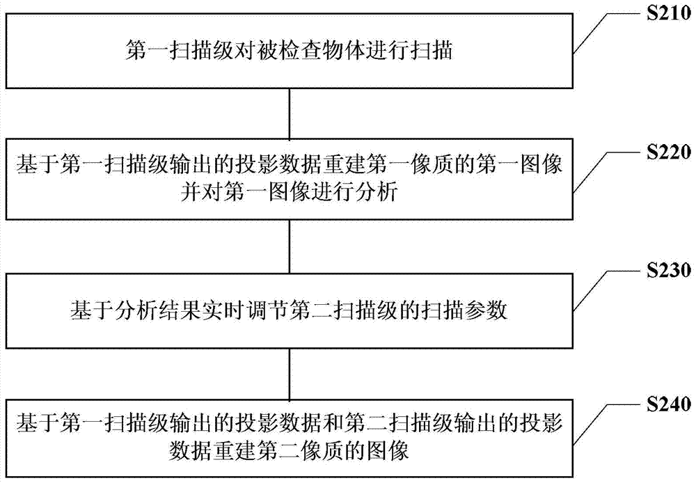
A CT system and method thereof are disclosed. The system includes: a transmission mechanism; a first scanning stage, which scans the object to be inspected to generate a first digital signal; a second scanning stage, which is arranged at a predetermined distance from the first scanning stage along the moving direction of the object to be inspected; a processing device , reconstructing a CT image of the first image quality of the inspected object based on the first digital signal, and analyzing the CT image; the control device adjusts the scanning parameters of the second scanning stage based on the analysis result of the processing device, so that the second scanning The stage outputs a second digital signal, and the processing device reconstructs a CT image of a second quality of the inspected object based on at least the second digital signal, wherein the second quality is higher than the first quality. This system makes full use of the advantages brought by the distributed light source instead of the traditional slip ring technology.

Description

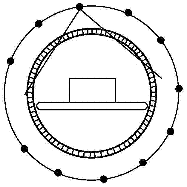
technical field [0001] Embodiments of the present invention relate to the field of radiation imaging safety detection, and in particular to a multi-source static CT baggage safety inspection system and method thereof. Background technique [0002] CT technology has played an important role in security inspection due to its ability to eliminate the effect of overlapping objects. Traditional CT uses a slip ring device to obtain projection data at different angles through the rotation of the X-ray machine and the detector, and obtains tomographic images through reconstruction methods to obtain the internal information of the detected luggage items. Cooperating with dual-energy or multi-energy imaging technology, the current luggage inspection equipment can reconstruct the atomic number and electron density of the substance to be inspected, so as to realize the identification of the substance type, which plays a very good role in the detection of explosives and dangerous goods. ...

Claims


Application Information

Patent Timeline
Patent Type & Authority Patents(China)
IPC IPC(8): G01N23/04
CPCG01V5/005G01N23/046G01T7/08G06T11/003G06T2207/10072G06T2211/40
Inventor 张丽陈志强黄清萍金鑫孙运达沈乐赵骥
Owner TSINGHUA UNIV
Learn More