Soil resistivity measurement method and device based on phase identification

A technology of soil resistivity and phase identification, which is applied in measuring devices, measuring electrical variables, measuring resistance/reactance/impedance, etc., to eliminate the influence of mutual inductance of voltage and current electrode leads, good anti-interference ability, anti-power frequency interference ability strong effect

Active Publication Date: 2015-02-25
EXAMING & EXPERIMENTAL CENT OF ULTRAHIGH VOLTAGE POWER TRANSMISSION COMPANY CHINA SOUTHEN POWER GRID
View PDF5 Cites 14 Cited by
  • Summary
  • Abstract
  • Description
  • Claims
  • Application Information

AI Technical Summary

Problems solved by technology

[0004] In view of this, the technical problem to be solved by the present invention is to provide a soil resistivity measurement device and me

Method used


Image

  • Soil resistivity measurement method and device based on phase identification
  • Soil resistivity measurement method and device based on phase identification
  • Soil resistivity measurement method and device based on phase identification

Examples


Embodiment 1

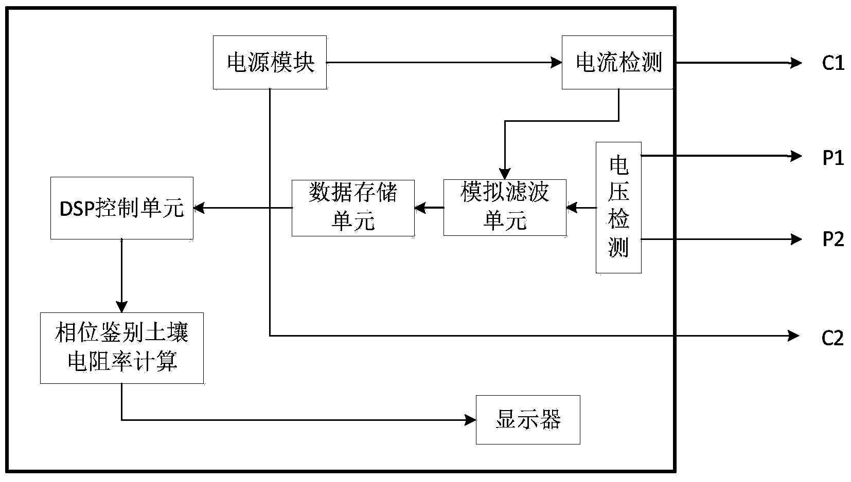
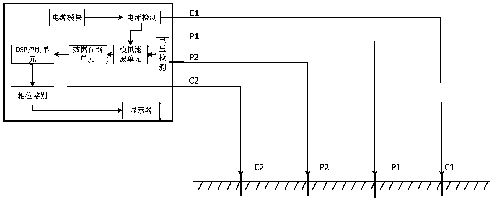
[0060] figure 1 Device wiring and working principle block diagram provided for the embodiment of the present invention, figure 2 The layout diagram of the voltage and current electrode leads provided for the embodiment of the present invention is shown in the figure: a method for measuring and testing anti-interference soil resistivity based on phase recognition provided by the present invention includes the following steps:

[0061] S1: Select the soil to be tested and insert the current electrode C1, voltage electrode P1, voltage electrode P2 and current electrode C2 on the surface along a straight line in sequence according to the preset electrode spacing;

[0062] S2: Select the positive-rotating waveform power supply according to the preset frequency, and inject the current signal I into the soil surface to be tested through the current pole C1 and the current pole C2,

[0063] S3: Measure the voltage signal U on the voltage pole P1 and the voltage pole P2;

[0064] S4...

Embodiment 2

[0111] The difference between this embodiment and embodiment 1 is only:

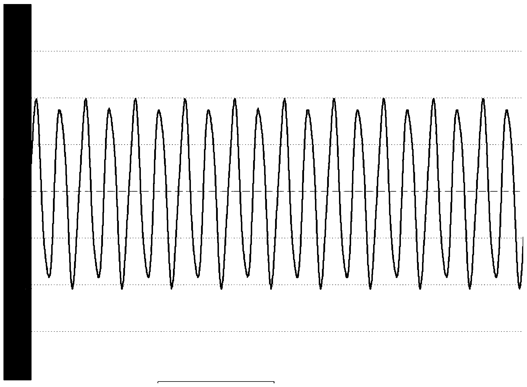
[0112] The schematic diagram of amplitude modulation waveforms of 50Hz and 125Hz voltage signals during actual measurement provided by this embodiment, as shown in Figure 3-4 as shown, image 3 The 125Hz provided for the embodiment of the present invention is 0.1 times the 50Hz signal; Figure 4 The 125Hz signal provided for the embodiment of the present invention is 0.7 times of 50Hz; Figure 5 The 125Hz signal provided for the embodiment of the present invention is twice that of the 50Hz signal;

[0113] This embodiment provides a comparison of the simulation test results considering the mutual inductance and not considering the mutual inductance, such as Figure 6-7 as shown, Figure 6 Consider the comparison of the simulation test results of mutual inductance and no mutual inductance under the 1000Ωm uniform soil resistivity provided for the embodiment of the present invention; Figure 7 Compar...

Embodiment 3

[0149] The difference between this embodiment and embodiment 1 is only:

[0150] The present embodiment provides a soil resistivity measurement device based on phase recognition and anti-lead mutual inductance interference, which mainly includes an auxiliary measurement electrode and a soil resistivity tester. Auxiliary measuring poles include multiple current poles and two voltage poles. The length of each pole is 50-60cm, and the size is ∠20×20×3. The poles are connected to the current port of the tester through wires, and the middle two electrodes are used as voltage electrodes to connect to the voltage port of the tester through wires. The soil resistivity tester consists of a current output module (using high-power power electronic devices as the frequency conversion output power supply, the current output range is 0-6A, with over-current protection function), a current detection module (using Rogowski coil for measurement and matching Industrial-grade A / D converter AD16...


PUM


Abstract

The invention discloses an anti-interference soil resistivity measurement method based on phase identification. The method comprises the first step of selecting soil to be measured and driving current electrodes and voltage electrodes into the earth surface in sequence along the straight line according to a preset electrode distance, the second step of selecting a power source according to a preset frequency, and injecting current signals into the earth surface of the soil to be measured through the current electrodes, the third step of measuring and getting voltage signals on the voltage electrodes, the fourth step of obtaining cophase components of the voltage signals and the current signals at the preset frequency through phase identification, and the last step of calculating the soil resistivity through a soil apparent resistivity formula. According to the method, 125-Hx measuring frequency different from 50-Hz power frequency is adopted, so good anti-interference capacity can be achieved even on triple-frequency harmonic, interference of lead mutual-inductance on an on-site soil resistivity electrical test result is effectively eliminated, and the measurement accuracy is improved. The method can be widely applied to resistivity measurement of the soil along power transmission lines or the soil in a substation and other places, is particularly suitable for measurement at a large electrode distance and can well eliminate influences of lead mutual-inductance of the voltage electrodes and the current electrodes.

Description

technical field [0001] The invention relates to the technical field of lightning protection and grounding, in particular to a measuring device and a testing method for soil resistivity in a site area when each grounding device is designed. Background technique [0002] Resistivity is one of the fundamental properties of matter. The resistivity of any substance can be defined as the resistance between the two sides of the substance per unit volume, in Ω. There are two-pole method, three-pole method and four-pole method commonly used on-site soil resistivity electrical testing methods. The two-pole method and the three-pole method are simple to operate, but the soil range of the measurement is generally not large, and the contact resistance between the test electrode and the soil medium will introduce a large error. The commonly used method for testing large-scale soil resistivity is the quadrupole method. Among them, the Wenner quadrupole method is widely used in engineerin...

Claims


Application Information

Patent Timeline
IPC IPC(8): G01R27/02
Inventor 陈伟卢文浩夏谷林
Owner EXAMING & EXPERIMENTAL CENT OF ULTRAHIGH VOLTAGE POWER TRANSMISSION COMPANY CHINA SOUTHEN POWER GRID
Why Eureka
Try Eureka