Driving mechanism of dual-power automatic transfer switch

An automatic transfer switch and driving mechanism technology, applied in the field of electromechanical manufacturing, can solve the problem of not preventing the main switch shaft from reversing, and achieve the effect of improving reliability and stability and increasing the self-locking of the mechanism

Inactive Publication Date: 2015-02-25
GUIZHOU TAIYONG CHANGZHENG TECH CO LTD
View PDF5 Cites 88 Cited by
  • Summary
  • Abstract
  • Description
  • Claims
  • Application Information

AI Technical Summary

Problems solved by technology

[0003] Disadvantages of this structure: the swing plate is directly hinged with the connecting plate, there is no lever mechanism in the middle, and the force of the electromagnet does not increase, which is equivalent to the clo

Method used


Image

  • Driving mechanism of dual-power automatic transfer switch
  • Driving mechanism of dual-power automatic transfer switch
  • Driving mechanism of dual-power automatic transfer switch

Examples


Embodiment Construction

[0014] The present invention will be described in detail below in conjunction with the accompanying drawings.

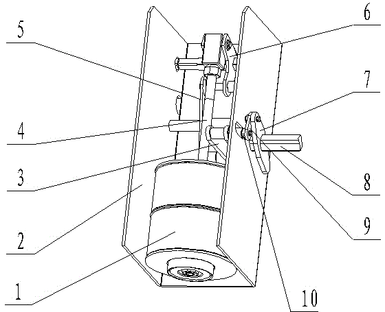
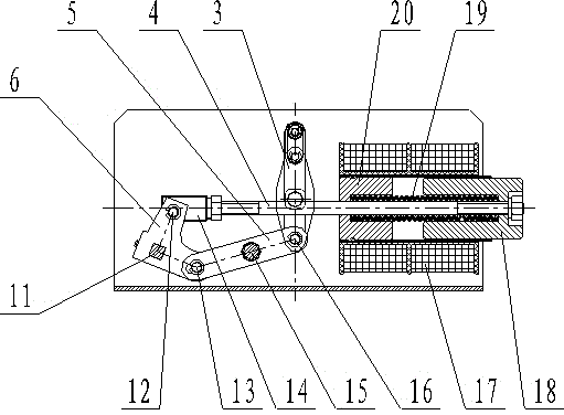
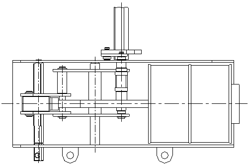
[0015] like figure 1 , figure 2 , image 3 As shown, the driving mechanism of the present invention mainly includes: driving electromagnet assembly 1, mounting bracket 2, connecting plate 3, push rod 4, lever 5, swinging plate 6, crank 7, main body switch shaft 8, connecting rod 9, Bearing pin 10,11 rotating shaft, hinge one 12, hinge two 13, connecting block 14, axle 15, hinge three 16, hinge four 21. The driving electromagnet assembly 1 includes: an excitation coil 17, a moving iron core 18, a spring 19, and a static iron core 20; the right end of the push rod 4 is fixed on the moving iron core 18, and the left end is fixed on the connecting block 14; the middle part of the swing plate 6 Fixed on the rotating shaft 11, it can rotate with the rotating shaft 11, and is connected with the connecting block 14 through the hinge shaft 12. The hinge shaft 12 is instal...


PUM


Abstract

The invention relates to a driving mechanism of a dual-power automatic transfer switch. The driving mechanism mainly comprises a driving electromagnet assembly, a mounting bracket, a connecting plate, a push rod, a lever, an oscillating deck, a crank, a main switch rotating shaft, a connecting rod, a pin shaft, a rotating shaft, a first hinged shaft, a second hinged shaft, a connecting block, a shaft, a third hinged shaft and a fourth hinged shaft; the driving electromagnet assembly is composed of a magnet exciting coil, a dynamic iron core, a spring and a static iron core. The driving mechanism is characterized in that in the driving electromagnet assembly, linear motion in the horizontal direction of the dynamic iron core and the push rod is converted into linear motion of the pin shaft in the vertical direction through the oscillating deck, the lever, the connecting plate and the like, and linear motion of the pin shaft is converted into swing of the main switch rotating shaft around the axis through the connecting rod and the crank. Reciprocating swing of the main switch rotating shaft completes switching on and switching off actions of the whole switch. The oscillating deck plays a role in changing the motion direction. The lever plays a role in increasing thrust. A connecting rod crank mechanism plays a role in self-locking and preventing reversion.

Description

technical field [0001] The invention belongs to the field of electromechanical manufacturing, and in particular relates to a driving mechanism for a double power supply automatic transfer switch. This mechanism is mainly used for PC-level dual-power automatic transfer switching appliances. This type of product has high reliable mechanical and electrical performance, fast switching speed, and strong breaking capacity. It is suitable for use category AC-33A. Background technique [0002] The driving mechanism of the existing dual-power automatic transfer switch usually adopts the moving iron core push rod of the electromagnet to connect the swing plate, the swing plate is hinged to the connecting plate, and the pin shaft on the connecting plate directly drives the rotating shaft to swing through the guide groove. [0003] Disadvantages of this structure: the swing plate is directly hinged with the connecting plate, there is no lever mechanism in the middle, the force of the el...

Claims


Application Information

Patent Timeline
IPC IPC(8): H01H3/32
CPCH01H3/32
Inventor 黄正乾董天亮
Owner GUIZHOU TAIYONG CHANGZHENG TECH CO LTD
Why Eureka
Try Eureka