Method and device for accurately locating fault point of optical cable

A technology for precise positioning and fault point, which is applied in the field of optical communication testing, can solve problems such as difficulties in maintenance and emergency repair, unobvious appearance characteristics of optical cables at fault points, and increased difficulty in fault point location

Active Publication Date: 2015-02-25
GUILIN G LINK TECH
View PDF8 Cites 20 Cited by
  • Summary
  • Abstract
  • Description
  • Claims
  • Application Information

AI Technical Summary

Problems solved by technology

However, if the external damage of the optical cable is small but the internal fiber breakage, broken strands, or excessive bending and other faults, the appearance of the damaged optical cable at the fault point is not obvious, and the positioning error of 50-200 meters will be large. The difficulty of l

Method used


Image

  • Method and device for accurately locating fault point of optical cable

Examples


Embodiment

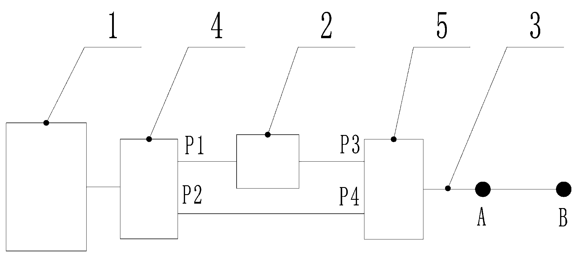
[0037] Reference figure 1 , A device for accurately locating the fault point of an optical cable, comprising an OTDR module 1, an optical fiber polarizer / analyzer 2, a first optical switch 4, and a second optical switch 5. The input / output end of the OTDR module 1 and the second optical switch The common end of an optical switch 4 is connected, and the two ports of the optical fiber polarizer / analyzer 2 are respectively connected to the transmission port P1 of the first optical switch 4 and the transmission port P3 of the second optical switch 5. The transmission port P2 is connected to the transmission port P4 of the second optical switch 5, and the common end of the second optical switch 5 is connected to the optical cable 3 under test.

[0038] The first optical switch and the second optical switch are both 1X2 optical switches.

[0039] Points A and B in the figure correspond to points A and B in the following method.

[0040] A method for accurately locating the fault point of...


PUM


Abstract

The invention discloses a method for accurately locating a fault point of an optical cable. The method includes the first step that the optical length Lb of an optical fiber of a fault point B is obtained; the second step that the length of the optical cable of a reference point A is 0.85*Lb-0.95*Lb; the third step that back scattering curve data D1 are obtained; the fourth step that back scattering curve data D2 are obtained; the fifth step that a data series D is obtained by subtracting D2 from D1, and the curve of D is represented by coordinates, wherein a Y-axis represents amplitude change of back scattering signals, and an X-axis represents the length of the optical fiber; the sixth step that displacement calculation is performed on the data series D, and the optical length of an optical fiber of a threshold point C is La; the seventh step that if the result subtracting La from Lb is smaller than 200m, A is the reference point, and if the result subtracting La from Lb is larger than 200m, the steps from the third step to the sixth step are repeated until the reference point A is found; the eighth step that the length Lc is obtained, and the actual position of the fault point can be obtained according to Lc and the final reference point A. The method has the advantages that the position of the fault point of the optical cable can be found quickly and accurately, the maintenance time is shortened, and work efficiency is improved. The invention further discloses a device for accurately locating the fault point of the optical cable.

Description

Technical field [0001] The invention relates to optical communication testing technology, in particular to a method and device for accurately locating fault points of optical cables. Background technique [0002] At present, the most convenient and commonly used tool for maintaining optical cable networks is Optical Time Domain Reflectometer (OTDR). The optical time domain reflectometer analyzes the working status of the optical fiber through the backscattered signal of the optical fiber, such as the attenuation of the optical fiber link, the quality of the connection point, the length of the optical fiber, whether it is excessively bent, etc. By analyzing the working state of the optical fiber, the working state of the optical cable can be roughly analyzed. Especially when the optical cable network fails, the fault point can be located by analyzing the attenuation curve of the optical fiber. Only after the fault point is located can the fault be eliminated and the optical cable...

Claims


Application Information

Patent Timeline
IPC IPC(8): H04B10/077
Inventor 刘丹蕾周晓伟彭怀敏肖丹谊雷静
Owner GUILIN G LINK TECH
Why Eureka
Try Eureka