Method and device for adjusting fiber feed to carding machine

A feeding device and fiber feeding technology, applied in fiber feeding, fiber treatment, textile and paper making, etc.

Active Publication Date: 2016-10-26
MASCHINENFABRIK RIETER AG
View PDF5 Cites 0 Cited by
  • Summary
  • Abstract
  • Description
  • Claims
  • Application Information

AI Technical Summary

Problems solved by technology

The disadvantage of this device is that the target pressure value is adjusted based on a predetermined filling level

Method used


Image

  • Method and device for adjusting fiber feed to carding machine
  • Method and device for adjusting fiber feed to carding machine

Examples


Embodiment Construction

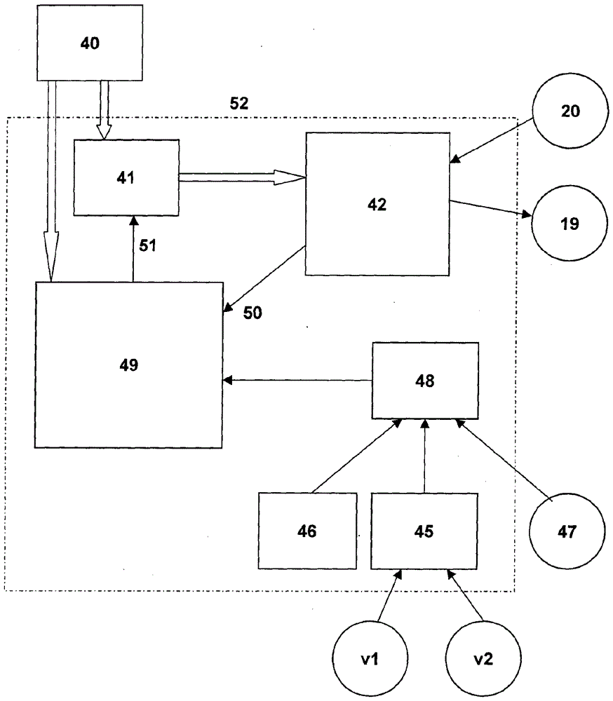
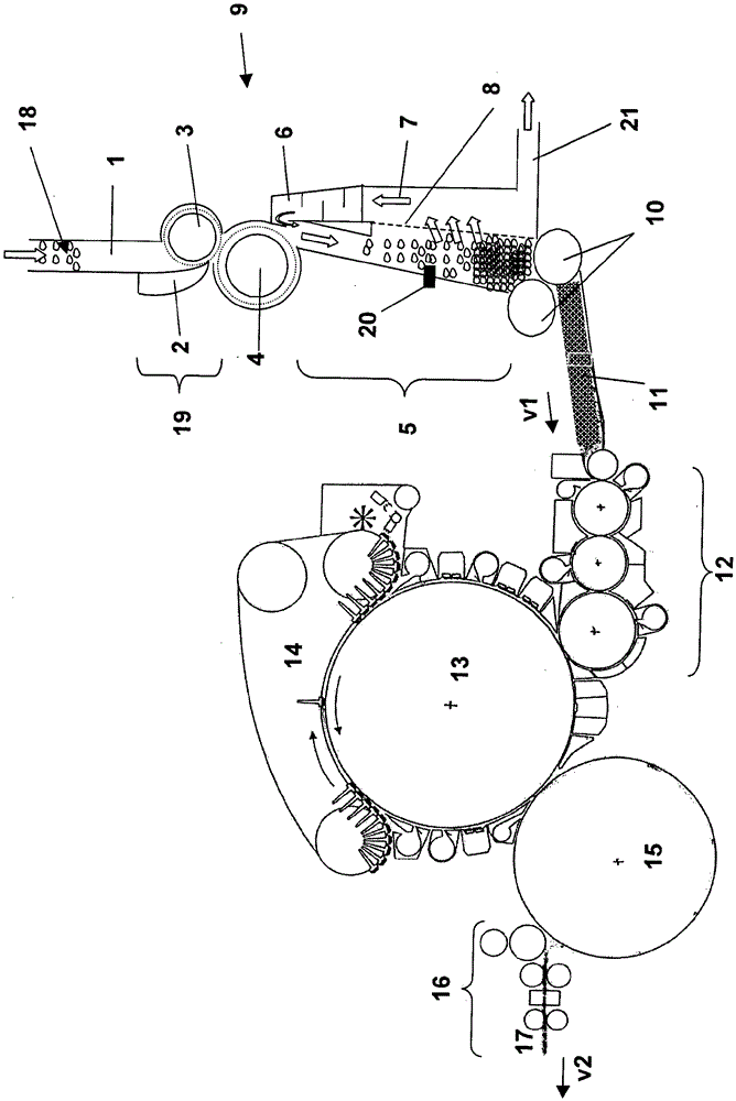
[0018] figure 1 A rotary flat card equipped with a feed box 9 is shown. After the fiber tow 18 has passed through the various process stages of the blowroom system, it enters the upper box 1 of the feeding box 9 . The fiber bundle 18 is transferred by a feed device 19 comprising a feed trough 2 and a feed roller 3 to the opening roller 4 , which further opens the fiber bundle 18 . The opening roller 4 transports the further opened fiber bundle 18 into the lower cotton box 5 . This opening roller 4 does not have to be present to ensure the adjustment of the batt weight, but the presence of said opening roller and the resulting fine opening of the fiber bundle does affect the compaction of the fiber bundle, while the pressure in the lower box 5 remains the same . A pressure sensor 20 for measuring the prevailing pressure is arranged in the lower hopper 5 . A blowing device 6 is provided in the cotton feeding box 9 for further compacting the batt. The blowing device blows mo...


PUM


Abstract

The invention relates to a device and a method for controlling the fiber feed to a carding machine having a filling shaft. The filling shaft is divided into an upper shaft and a lower shaft, wherein fiber flocks are fed into the upper shaft and are transported into the lower shaft (5) by means of a feeding device (19). The fiber flocks are compressed into wadding having a certain wadding weight in the lower shaft under a certain pressure. A target value for the wadding weight is predefined, with which target value a pressure for the lower shaft is associated. Then an actual value of the wadding weight is determined and the target value for the pressure is corrected on the basis of a comparison of the target value and actual value of the wadding weight.

Description

technical field [0001] The present invention relates to a method and a device for adjusting the fiber feed to a carding machine. Background technique [0002] Cards are used in spinning preparation to open fiber material into individual fibers, to parallelize these individual fibers, and to clean these fibers of impurities. The carding machine produces carded sliver from the fed fiber material, wherein the carded sliver is then further processed to form yarn. Instead of card sliver, fiber webs (webs) can also be produced. Below, the fiber web produced by the card is considered to be a card sliver. In this regard, the carding machine is usually assigned a feed chute which is supplied with fibers from the blowroom via a conveying system. The fibers are delivered in this case in the form of fiber bundles. From the feed box, the fiber bundles are introduced into the carding machine in the form of batts. The uniformity of the batt entering the carding machine plays an import...

Claims


Application Information

Patent Timeline
IPC IPC(8): D01G23/04
CPCD01G23/04D01G23/06
Inventor C.米勒
Owner MASCHINENFABRIK RIETER AG
Why Eureka
Try Eureka