A signal transmission and detection method, transceiver, and control entity
A technology for controlling entities and signal transmission, applied in the field of communication, which can solve the problems of false activation, inability to guarantee the accuracy of message transmission, robustness, strong signal correlation, etc.
- Summary
- Abstract
- Description
- Claims
- Application Information
AI Technical Summary
Problems solved by technology
Method used
Image
Examples
specific Embodiment approach 1
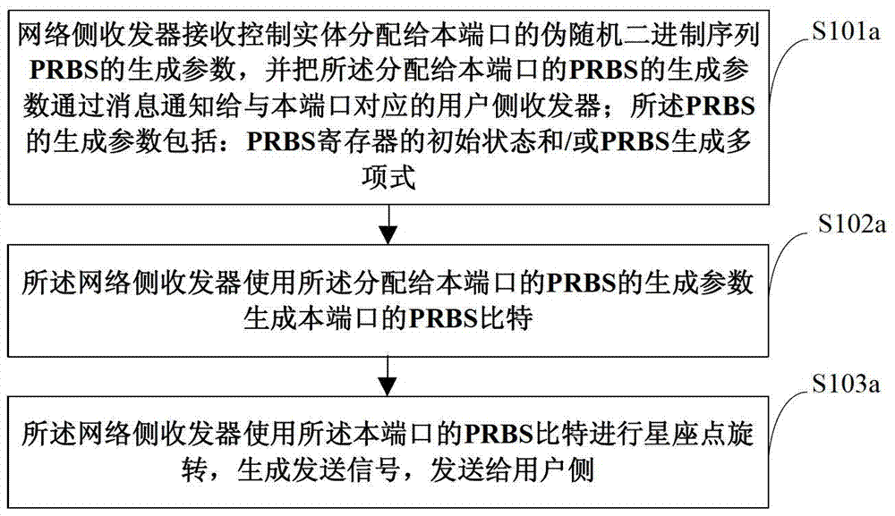
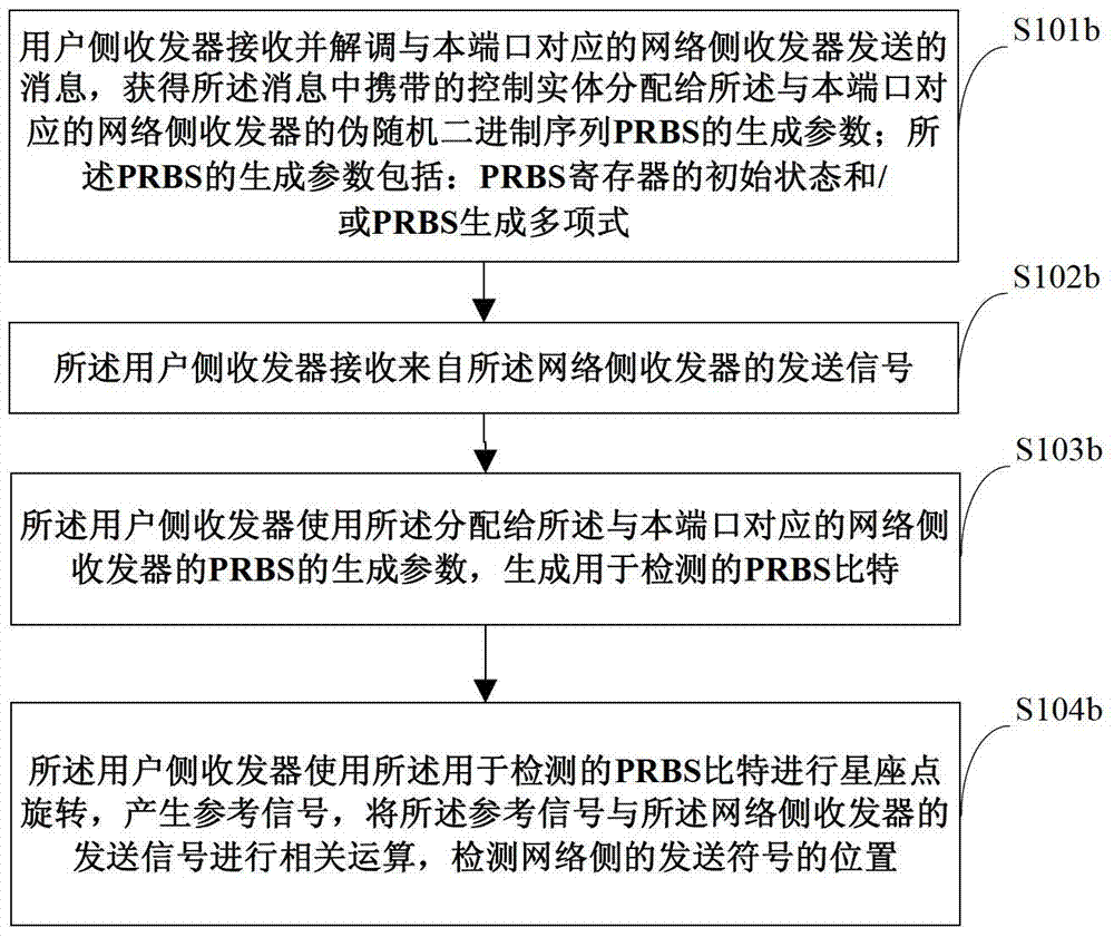
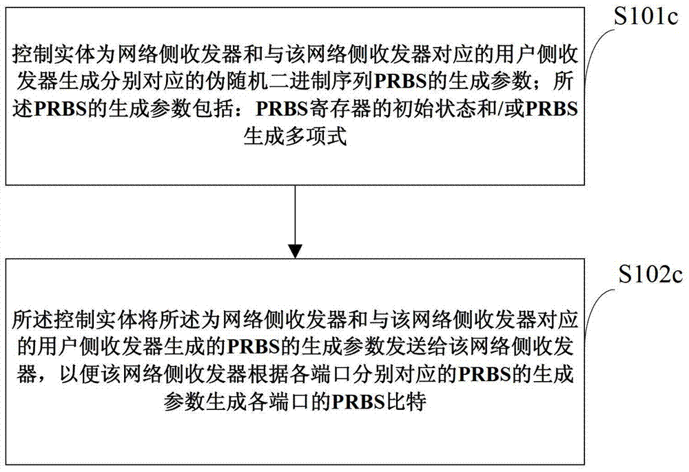
[0088] In the first embodiment, all network-side transceivers and corresponding user-side transceivers use the same PRBS generator polynomial, and design the corresponding initial state of the PRBS register for each network-side transceiver and its corresponding user-side transceivers . Wherein, an initial state of the PRBS register different from that of other network-side transceivers may be designed for all or part (a part with stronger crosstalk) of the network-side transceiver. Wherein, the initial states of the PRBS registers of the network-side transceiver and the corresponding user-side transceiver may be the same or different, and may be specifically set according to actual conditions.
[0089] It should be noted that, in the following specific embodiments of the present invention, unless otherwise stated, the initial state of the PRBS register designed for each network-side transceiver and other network-side transceivers is taken as an example for illustration . Th...
specific Embodiment approach 2
[0157] All network-side transceivers and corresponding user-side transceivers use the same PRBS generator polynomial, and an initial state of a corresponding PRBS register is designed for each network-side transceiver and its corresponding user-side transceiver. Specifically, the control entity uses the port number of the FTU-O to generate the initial state of the PRBS register corresponding to the FTU-O; uses the port number of the FTU-R to generate the initial state of the PRBS register corresponding to the FTU-R. Of course, in practical applications, the port numbers of the FTU-O and the corresponding FTU-R are consistent.
[0158] refer to Figure 5 , is a flow chart of the signal sending and detecting method described in Embodiment 2 of the present invention. Such as Figure 5 As shown, the method may include the following steps:
[0159] Step S301: the user powers on and enters the Handshake stage, where the FTU-O and the FTU-R interact to generate a PRBS.
[0160] I...
specific Embodiment approach 3
[0176] refer to Image 6 , is a flow chart of the method for signal transmission and detection described in Embodiment 3 of the present invention. Such as Image 6 As shown, the method may include the following steps:
[0177] Step S401: the user powers on and enters the Handshake stage, where the FTU-O and the FTU-R interact to generate a PRBS.
[0178] In the third embodiment of the present invention, the generation mode of the PRBS is still: all users adopt the same PRBS generator polynomial, and utilize the port number information of the FTU-O corresponding to each user to generate the FTU-O and FTU-O of each user. R respectively corresponds to the initial state of the PRBS register.
[0179] Step S402: The FTU-O generates the initial state of the PRBS register of the port and the FTU-R corresponding to the port according to the port number information of the port.
[0180] Step S403: The FTU-O notifies the FTU-R corresponding to the port of the initial state of the PR...
PUM
 Abstract
Description
Claims
Application Information
 - R&D
- Intellectual Property
- Life Sciences
- Materials
- Tech Scout
- Unparalleled Data Quality
- Higher Quality Content
- 60% Fewer Hallucinations
Browse by: Latest US Patents, China's latest patents, Technical Efficacy Thesaurus, Application Domain, Technology Topic, Popular Technical Reports.
© 2025 PatSnap. All rights reserved.Legal|Privacy policy|Modern Slavery Act Transparency Statement|Sitemap|About US| Contact US: help@patsnap.com


