

Perforated cleaner for optical lenses
A technology for cleaning equipment and optical lenses, applied in liquid cleaning methods, chemical instruments and methods, cleaning methods and utensils, etc., can solve the problems of poor cleaning effect and long cleaning time, so as to prevent lens from falling and increase stability Enhanced performance and stability
- Summary
- Abstract
- Description
- Claims
- Application Information
AI Technical Summary
Problems solved by technology
Method used
Image

Examples
Embodiment Construction
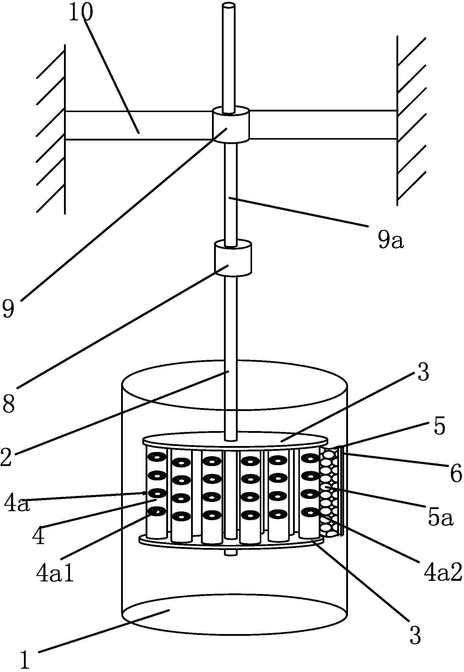
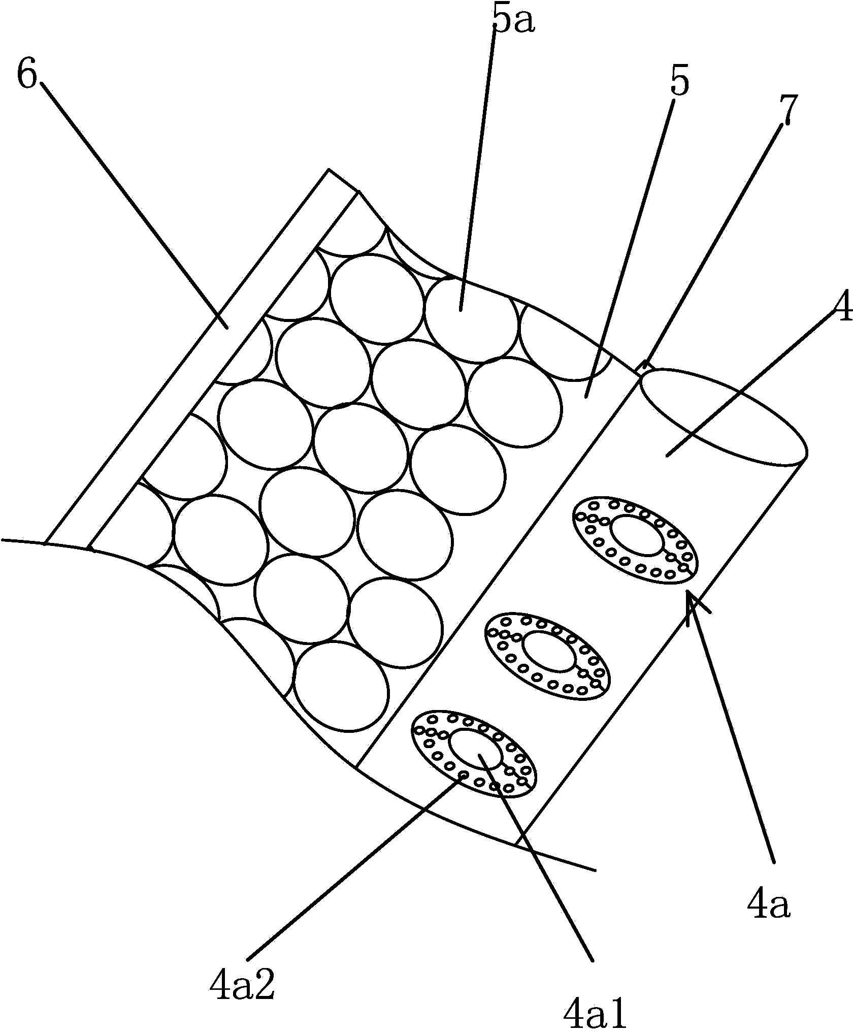
[0030] Such as figure 1 and figure 2 As shown, the cell cleaning equipment used for optical lenses includes a barrel-shaped cleaning barrel 1 with an opening at the upper end. The cleaning barrel 1 has a loading mechanism extending from the opening. The loading mechanism includes a vertically arranged loading shaft 2 And two loading boards 3 arranged in parallel and fixedly connected on the loading shaft 2, there are several cylindrical columns 4 between the two loading boards 3, and the outer wall of the column 4 has a plurality of optical The ellipsoidal lens groove 4a of the lens, the lens groove 4a is in the shape of a constriction and the bottom center of the lens groove 4a has a bottom hole 4a1 that runs through both sides of the column 4, and the two ends of the lens are located on the outer walls of both sides of the column 4. The groove 4a has a plurality of water passage holes 4a2 that run through both sides of the column 4, and the outer wall of one of the columns...
PUM
 Abstract
Description
Claims
Application Information