Overconstrained parallel mechanism with equivalent Tricept mechanical movement
A mechanism motion, over-constrained technology, applied in manipulators, manufacturing tools, program-controlled manipulators, etc., can solve the problem of reducing the number of joints, and achieve the effect of fewer joints, excellent motion characteristics, and simple structure
- Summary
- Abstract
- Description
- Claims
- Application Information
AI Technical Summary
Problems solved by technology
Method used
Image
Examples
Embodiment 1
[0015] Specific embodiments of the present invention will be described in detail below in conjunction with the accompanying drawings.
[0016] Example 1
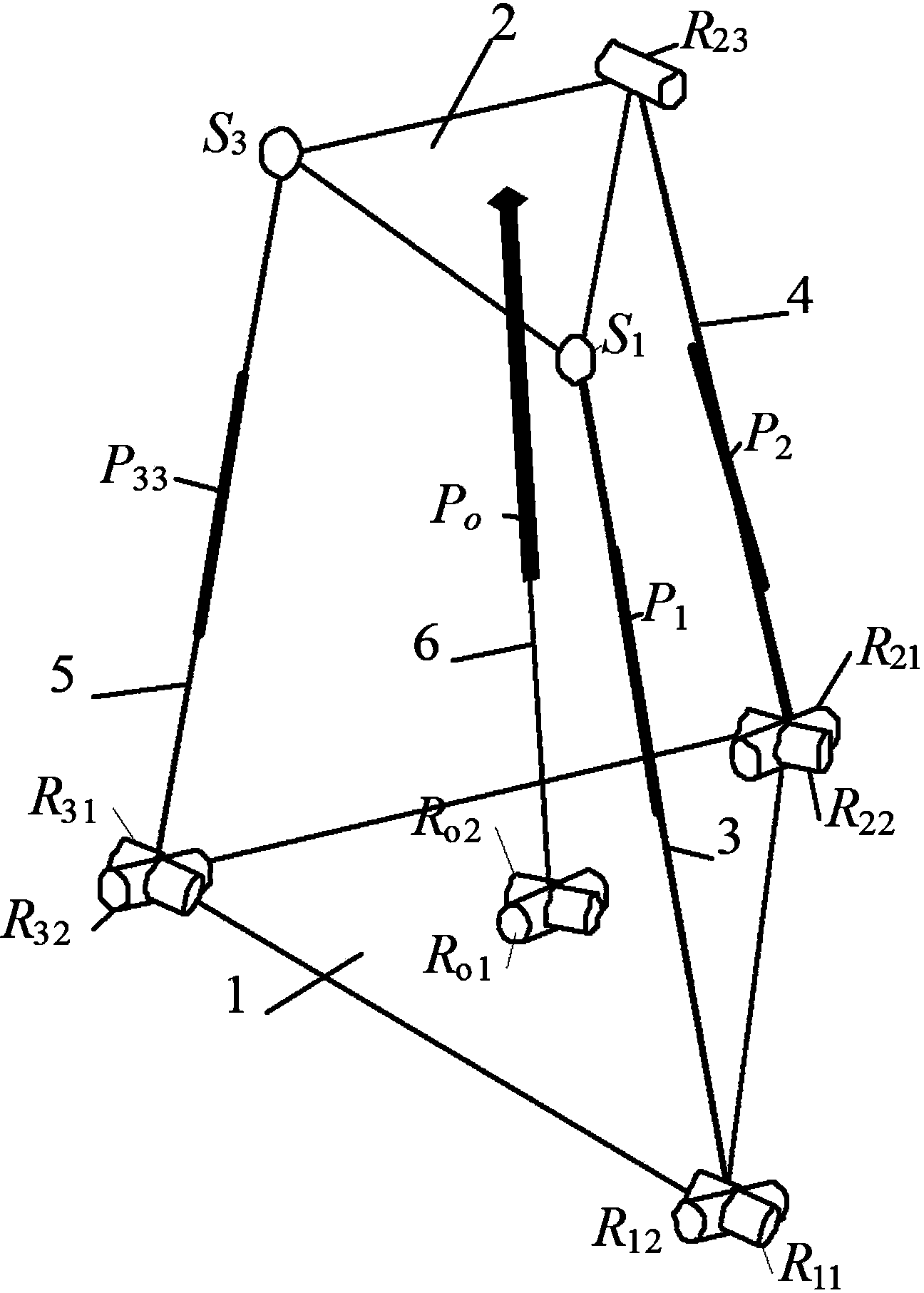
[0017] figure 1 It is the first embodiment disclosed by the present invention. An over-constrained parallel mechanism with equivalent Tricept mechanism movement described in the present invention includes a fixed platform 1 , a moving platform 2 , three drive branches ( 3 , 4 , 5 ) connecting them and an intermediate constraint branch 6 . Among them, the fixed platform 1 and the moving platform 2 are equilateral triangles, the two ends of the three driving branches (3, 4, 5) are respectively connected to the three vertices of the fixed platform 1 and the moving platform, and the constraint branch 6 in the middle is connected to the fixed platform 1 and center of moving platform 2.
[0018] Universal hinges ( R 11 , R 12 ), mobile vice ( P 1 ) and ball pair (S 1 ), the outer rotating pair of the universal joint ( R...
Embodiment 2
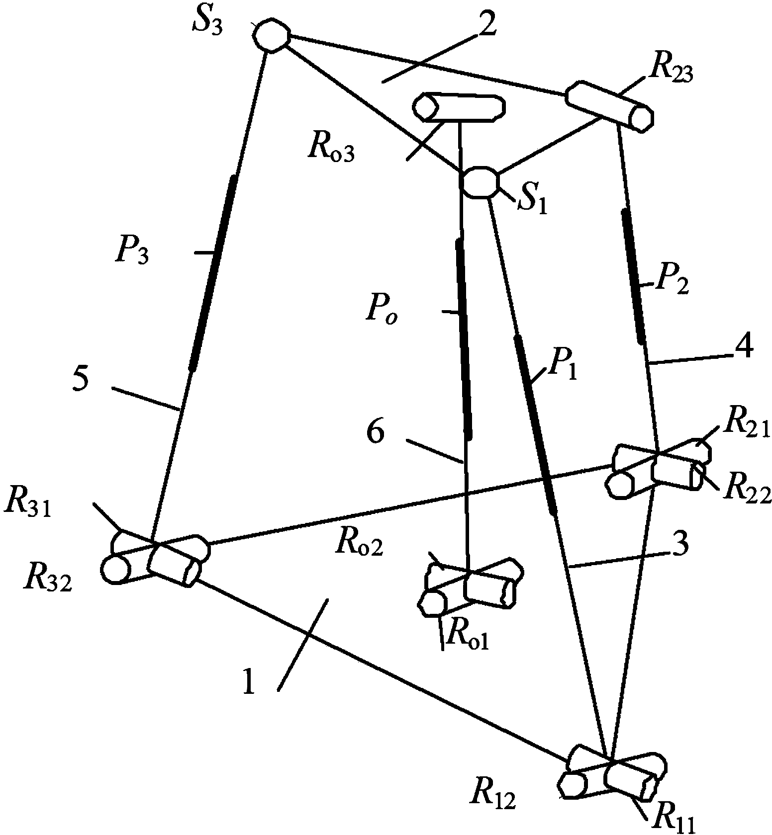
[0020] figure 2 It is the second embodiment disclosed by the present invention. figure 2 Among them, the constraint branch 6 in the middle is a UPR branch, and the universal hinge ( R 01 , R 02 ), mobile vice ( P 0 ) and rotating pair ( R 03 ). Outer turning pair of universal joint ( R 01 ) is connected with the center of the fixed platform 1, its axis points to the lower end point of the second branch 4, and is connected with the second branch 4 universal hinge outer rotation pair ( R 21 ) are collinear, and the inner rotating pair of the universal joint ( R 02 ) perpendicular to the revolving joint in the branch ( R 03 ), and with the moving pair in the branch ( P 0 ) vertically, the revolving pair ( R 03 ) is connected with the moving platform 2, and its axis points to the upper end point of the second branch 4. The other parts are connected in the same manner as in Example 1.
Embodiment 3
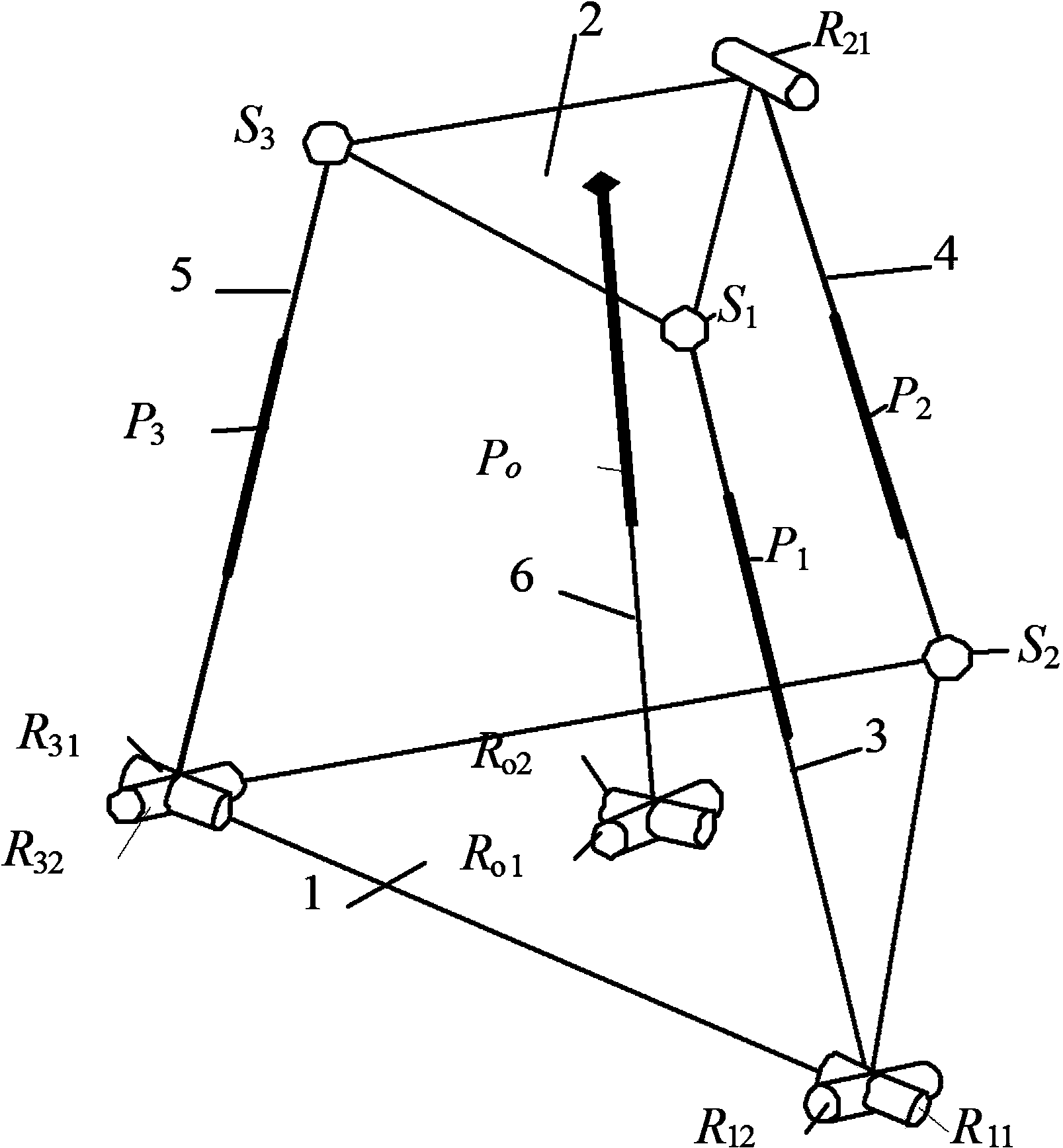
[0022] image 3 It is the third embodiment disclosed by the present invention. image 3 Among them, the second branch 4 is an SPR branch, and the second branch 4 is sequentially connected with ball pairs (S 2 ), mobile vice ( P 2 ) and rotating pair ( R 21 ). Among them, the ball pair (S 2 ) is connected to the fixed platform 1, and the rotating pair ( R 21 ) is connected with the moving platform 2, its axis is parallel to the opposite side of the moving platform 2, and the moving pair P 2 vertical. The other parts are connected in the same manner as in Example 1.
PUM
 Abstract
Description
Claims
Application Information
 - R&D
- Intellectual Property
- Life Sciences
- Materials
- Tech Scout
- Unparalleled Data Quality
- Higher Quality Content
- 60% Fewer Hallucinations
Browse by: Latest US Patents, China's latest patents, Technical Efficacy Thesaurus, Application Domain, Technology Topic, Popular Technical Reports.
© 2025 PatSnap. All rights reserved.Legal|Privacy policy|Modern Slavery Act Transparency Statement|Sitemap|About US| Contact US: help@patsnap.com


