Microminiature wheeling-walking combined wall climbing robot mechanism

A wall-climbing robot and composite technology, which is applied in the directions of motor vehicles, transportation and packaging, can solve the problems of poor motion performance, complex structure and high power consumption, and achieve the effects of good motion characteristics, flexible motion and wide application range.

Active Publication Date: 2009-04-29
SHENYANG INST OF AUTOMATION - CHINESE ACAD OF SCI
View PDF0 Cites 5 Cited by
  • Summary
  • Abstract
  • Description
  • Claims
  • Application Information

AI Technical Summary

Problems solved by technology

[0003] In order to overcome the shortcomings of the above-mentioned mobile mechanism, such as complex structure, heavy weight, high power consumption and poor motion performance, the present invention proposes a new type of micro-wheel-foot composite wall-climbing robot mechanism, which organically combines the movement speed of the wheel mechanism. The advantages of the fast and footed mechanism with strong obstacle-surmounting ability have achieved the goals of fast moving speed, light weight, low energy consumption and strong athletic ability

Method used


Image

  • Microminiature wheeling-walking combined wall climbing robot mechanism
  • Microminiature wheeling-walking combined wall climbing robot mechanism
  • Microminiature wheeling-walking combined wall climbing robot mechanism

Examples


Embodiment 1

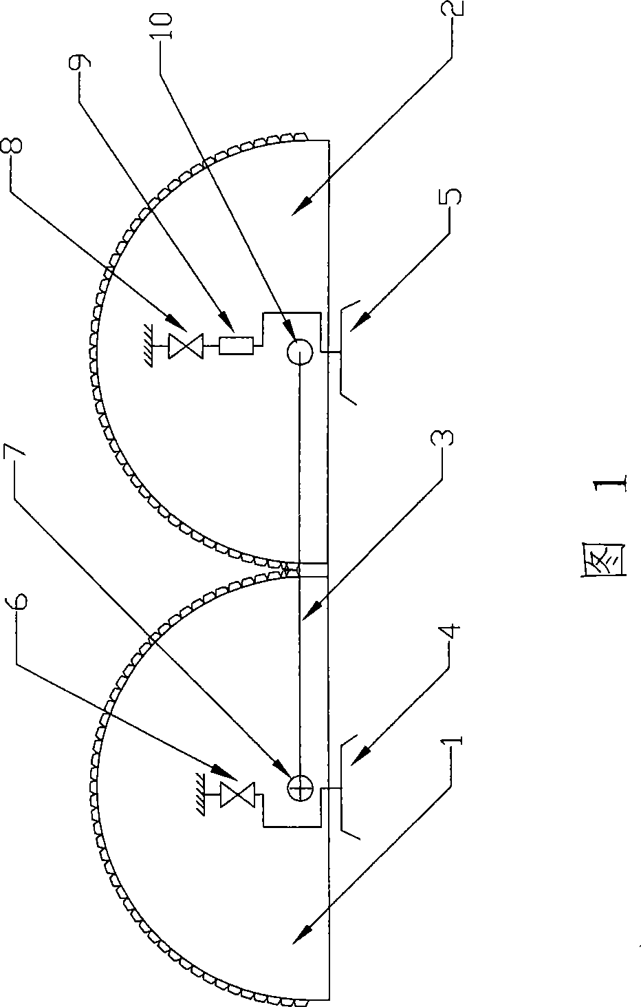
[0036] As shown in Figure 1, the mechanical structure of the present invention consists of a first body 1, a second body 2, a connecting rod 3, a first suction cup foot 4 connected to a vacuum pump, and a second suction cup foot 5, wherein: the first body 1 and the second suction cup foot The two bodies 2 are connected by the connecting rod 3 through the second revolving joint 7 and the fourth revolving joint 10, the first sucker foot 4 is connected with the first body 1 through the first revolving joint 6 (vertical setting), and the second sucker foot 5 is connected by mutual The third rotary joint 8 (vertical setting) and the first mobile joint 9 (vertical setting) in series are connected with the second body 2; the first rotary joint 6, the second rotary joint 7, the third rotary joint 8, the first mobile joint 9 are respectively connected with the motor drive.

[0037] The mechanism of the present invention has four degrees of freedom. The first rotary joint 6, the second ...

Embodiment 2

[0045]As shown in FIG. 6 , the difference between the mechanism of the present invention and Embodiment 1 is that the fourth rotating joint 11 (set horizontally) replaces the moving joint 9 . Compared with Example 1, Example 2 realizes the spanning of the crossing wall surface of the inventive mechanism by means of the fourth rotary joint 11 .

Embodiment 3

[0047] As shown in Figure 7, the difference between the mechanism of the present invention and Embodiment 1 is that the fourth rotary joint 10 on the second sucker foot 5 is removed, and a second moving joint 12 is added on the connecting rod (horizontally arranged, with the connecting rod same direction) to realize the relative movement between the two half cylinders.


PUM


Abstract

The invention relates to a movable robot mechanism, in particular to a mini biped-wheel composite wall-climbing robot mechanism comprising two main bodies, a link rod and two sucker feet. The two main bodies are respectively connected with the sucker feet and are mutually connected by adopting a rotary joint and through the link rod so as to realize the comparative rolling by the two main bodies; wherein, one main body is also provided with a rotary joint which is driven by a motor and arranged vertically and the other main body is provided with a moving joint which is driven by a motor and arranged vertically and a rotary joint arranged vertically so as to locally turn the whole robot mechanism and fold or unfold the sucker feet; and the movement and attitude regulation of the robot can be realized through the comparative rolling of the two main bodies and by alternately absorbing and releasing the two sucker feet. The mechanism integrates the high moving speed of wheel mechanism with the obstacle avoidance capability of foot mechanism so as to realize the aims of high moving speed, light weight, low energy-cost and high moving capability.

Description

technical field [0001] The invention relates to a mobile robot mechanism, in particular to a wall-climbing robot mechanism designed based on the principle of planetary gear train and bipedal vacuum adsorption. Background technique [0002] In the micro-miniature wall-climbing robot mechanism of prior art, most adopt the mobile mechanism of leg-foot type (document 1: S.W.Ryu, J.J.Park, S.M.Ryew, H.R.Choi, Self-contained Wall-climbing Robot with Closed Link Mechanism, IEEE International Conference on Intelligent Robots and Systems; Literature 2: Satya P.Krosuri and Mark A.Minor, AMultifunctional Hybrid Hip Joint for Improved Adaptability in MiniatureClimbing Robots), or use a reconfigurable mechanism composed of multiple unit modules (Document 3: Mark Yim, David G.Duff, Kimon D.Roufas, Walk on a Wild Side, IEEE Robotics & Automation Magazine Dec 2002;), the adsorption method mostly adopts negative pressure adsorption (Document 3: Application of wall-climbing robot technology, ...

Claims


Application Information

Patent Timeline
Patent Type & Authority Applications(China)
IPC IPC(8): B62D57/024
Inventor 王洪光刘爱华房立金景凤仁
Owner SHENYANG INST OF AUTOMATION - CHINESE ACAD OF SCI
Why Eureka
Try Eureka