Shock absorber

a technology of shock absorber and shock absorber, which is applied in the direction of shock absorber, vibration damper, spring/damper, etc., can solve the problems of shock absorber not being able to control the damping force characteristics in response, deterioration of driving comfort, and inability to ensure vehicle stability, etc., to improve the motional characteristics of the floating piston, and reduce the damping force

Active Publication Date: 2011-10-04
HL MANDO CORP
View PDF9 Cites 6 Cited by
  • Summary
  • Abstract
  • Description
  • Claims
  • Application Information

AI Technical Summary

Benefits of technology

[0015]According to an aspect, a shock absorber is provided that can change a fluid resistance with respect to a floating piston at any intended location within a hollow chamber to improve motional characteristics of the floating piston at that location.
[0016]Another aspect of the invention is to provide a shock absorber that includes a resistance changing mechanism configured to prevent the floating piston, disposed in the hollow chamber of a piston rod to lower a damping force, from completely closing an upper chamber and a lower chamber of the hollow chamber, so that the shock absorber can noticeably reduce the damping force in a region where the piston rod repetitiously moves, can gradually reduce the damping force according to a displacement of the piston rod to improve driving comfort and stability of the vehicle, and has a superior degree of freedom in tuning for lowering the damping force.
[0017]A further aspect of the invention is to provide a shock absorber that includes a mechanism configured to increase a fluid resistance with respect to the floating piston where the floating piston comes near the upper or lower end of the hollow chamber to prevent a contact impact between the floating piston and the upper or lower end of the hollow chamber while the floating piston is raised or lowered.

Problems solved by technology

Therefore, a low damping force characteristic can improve driving comfort but does not ensure stability of the vehicle, whereas a high damping force characteristic can maintain the stable posture of the vehicle but entails deterioration of driving comfort.
As such, the conventional shock absorber is incapable of controlling damping force characteristics in response to variation of the road state or the posture of the vehicle.
In this regard, when increasing the size of the hollow chamber 20 to improve the effect of reducing the damping force, there are problems of a manufacturing cost increase and a durability deterioration of the piston rod 14.
Furthermore, the conventional shock absorber 10 is likely to suffer impact and noise resulting from collision between the floating piston and the upper or lower end of the hollow chamber when the floating piston is raised or lowered within the hollow chamber of the piston rod.

Method used


Image

  • Shock absorber
  • Shock absorber
  • Shock absorber

Examples


Embodiment Construction

[0035]Some embodiments will be described in detail with reference to the accompanying drawings hereinafter.

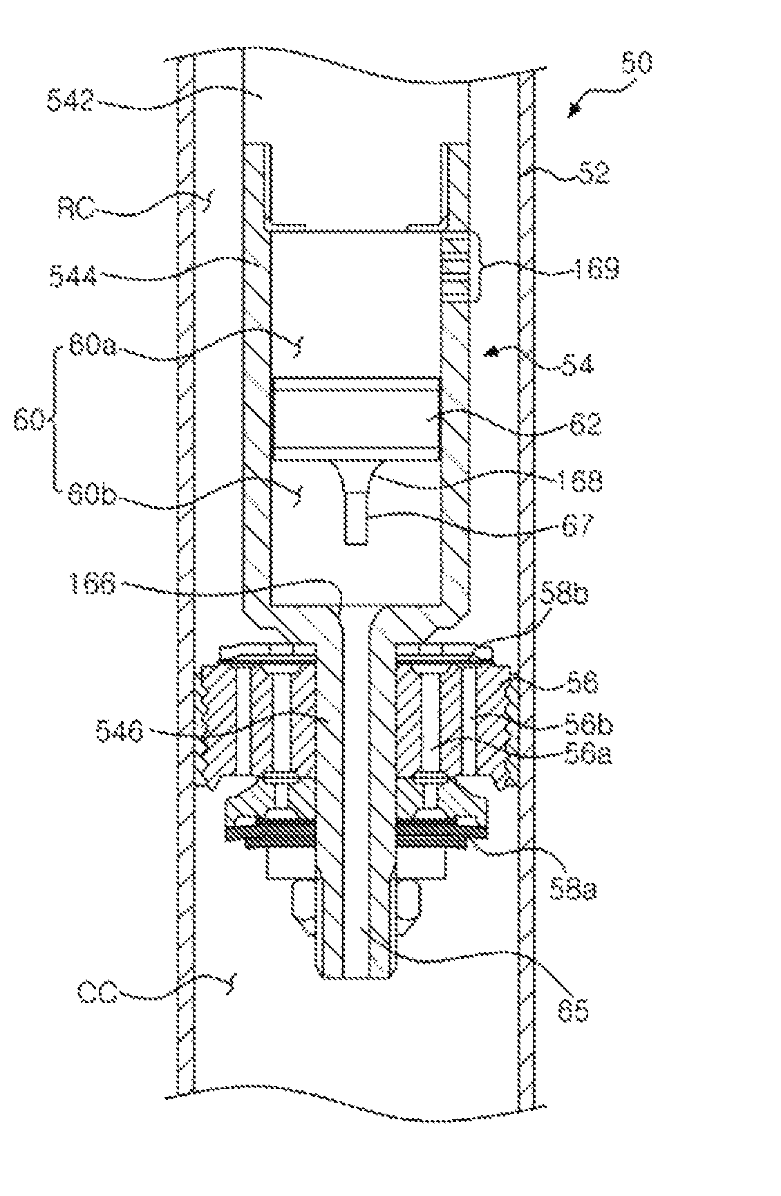
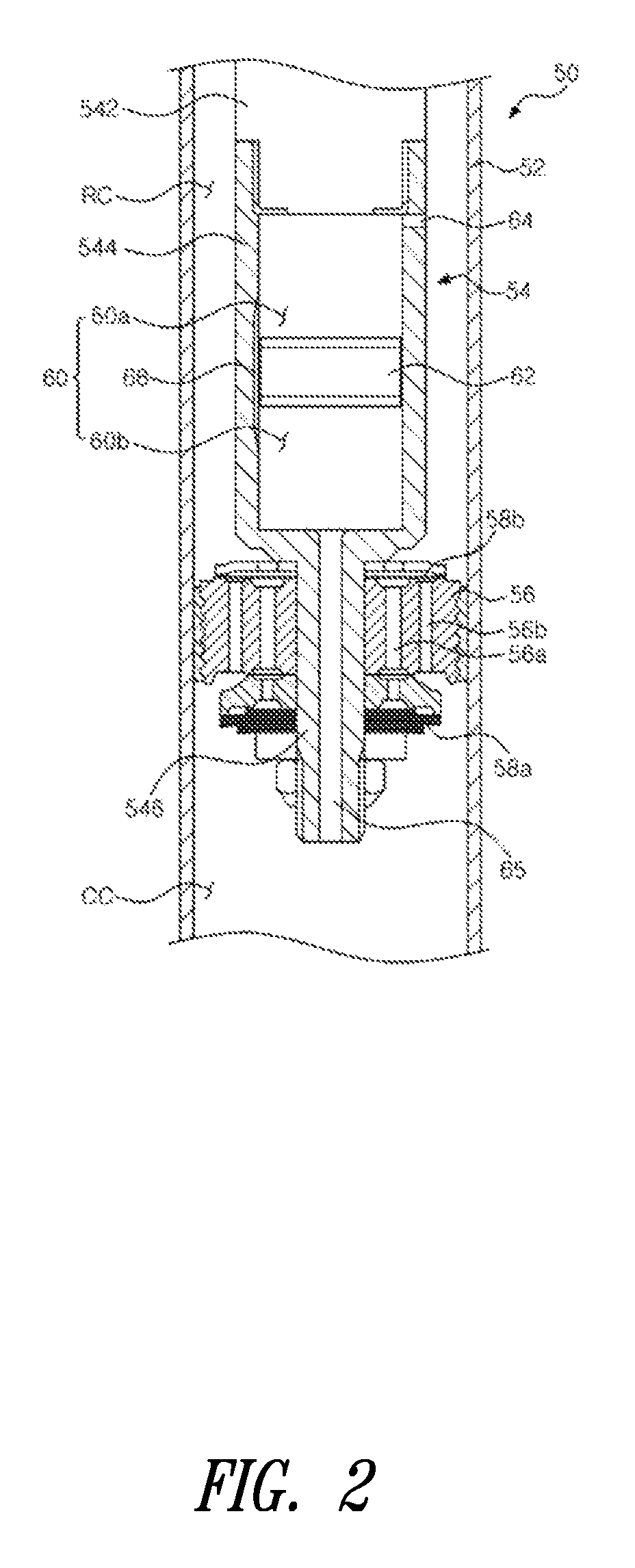
[0036]FIG. 2 is an enlarged cross-sectional view of a portion of a shock absorber according to one embodiment of the present invention.

[0037]Referring to FIGS. 2 and 3, a shock absorber 50 includes a cylinder 52 connected to an axle of the vehicle and a piston rod 54 connected to a vehicle body side. The piston rod 54 is disposed within the cylinder 52 to reciprocate therein and includes a piston valve 56 disposed at one end of the piston rod 54 to divide the cylinder 52 into a compression chamber CC and a tensile chamber RC. The piston valve 56 is formed with tensile orifices 56a and compression orifices 56b through which the tensile chamber RC communicates with the compression chamber CC. Further, a plurality of disc valves 58a and 58b are located on upper and lower surfaces of the piston valve 56 to elastically deform and generate a damping force according to movement of an ...


PUM


Abstract

Disclosed herein is a shock absorber for damping vibration transmitted to a vehicle according to a road state. The shock absorber includes a cylinder and a piston valve disposed within the cylinder and connected to a piston rod to divide the cylinder into a first chamber and a second chamber. The shock absorber further includes a hollow chamber formed within the piston rod, a floating piston disposed within the hollow chamber to move up and down and to divide the hollow chamber into upper and lower chambers, first and second orifices formed in upper and lower ends of the hollow chamber and connected to the first and second chambers, respectively, and a resistance changing mechanism configured to cooperate with the floating piston and change a fluid resistance with respect to the floating piston where the resistance changing mechanism cooperates therewith.

Description

BACKGROUND[0001]1. Technical Field[0002]The present disclosure is generally related to shock absorbers, and more particularly, to a shock absorber for damping vibration transmitted to a vehicle according to a road state and capable of changing a damping force according to a displacement of a piston rod.[0003]2. Description of the Related Art[0004]Generally, a vehicle is provided with a suspension system for enhancing driving comfort by buffering impact or vibration transmitted to an axle from a road during driving. One component constituting the suspension system is a shock absorber. The shock absorber is disposed between the axle and a vehicle body. The shock absorber includes a cylinder and a piston rod reciprocating within the cylinder. The cylinder is filled with an operating fluid, such as gas or oil, such that the operating fluid is moved by a piston valve secured to one end of the piston rod to generate a damping force.[0005]A conventional shock absorber has a restriction in ...

Claims


Application Information

Patent Timeline
Patent Type & Authority Patents(United States)
IPC IPC(8): F16F9/36
CPCF16F9/5126F16F9/32F16F9/34
Inventor KIM, NAM HO
Owner HL MANDO CORP
Why Eureka
Try Eureka