
Positioning device for shaft workpiece with gradient section

A technology of positioning device and section axis, applied in positioning devices, metal processing machinery parts, manufacturing tools, etc., can solve the problems of axial movement, unstable positioning, etc., to prevent axial movement, stable workpiece positioning, and prevent The effect of radial movement

Inactive Publication Date: 2015-03-04
CHONGQING HANGFEI MACHINERY MFG
View PDF0 Cites 3 Cited by
  • Summary
  • Abstract
  • Description
  • Claims
  • Application Information

AI Technical Summary

Problems solved by technology

[0003] We know that in the processing of shaft workpieces, the shaft must be milled, which requires the positioning of shaft workpieces. There are often the following problems in the processing and positioning of shafts: because this type of shaft has a gradual cross section, when positioning this type of shaft, axial movement often occurs and the positioning is unstable

Method used


Image

  • Positioning device for shaft workpiece with gradient section

Examples


Embodiment Construction

[0011] Below in conjunction with accompanying drawing and specific embodiment the present invention will be described in further detail:

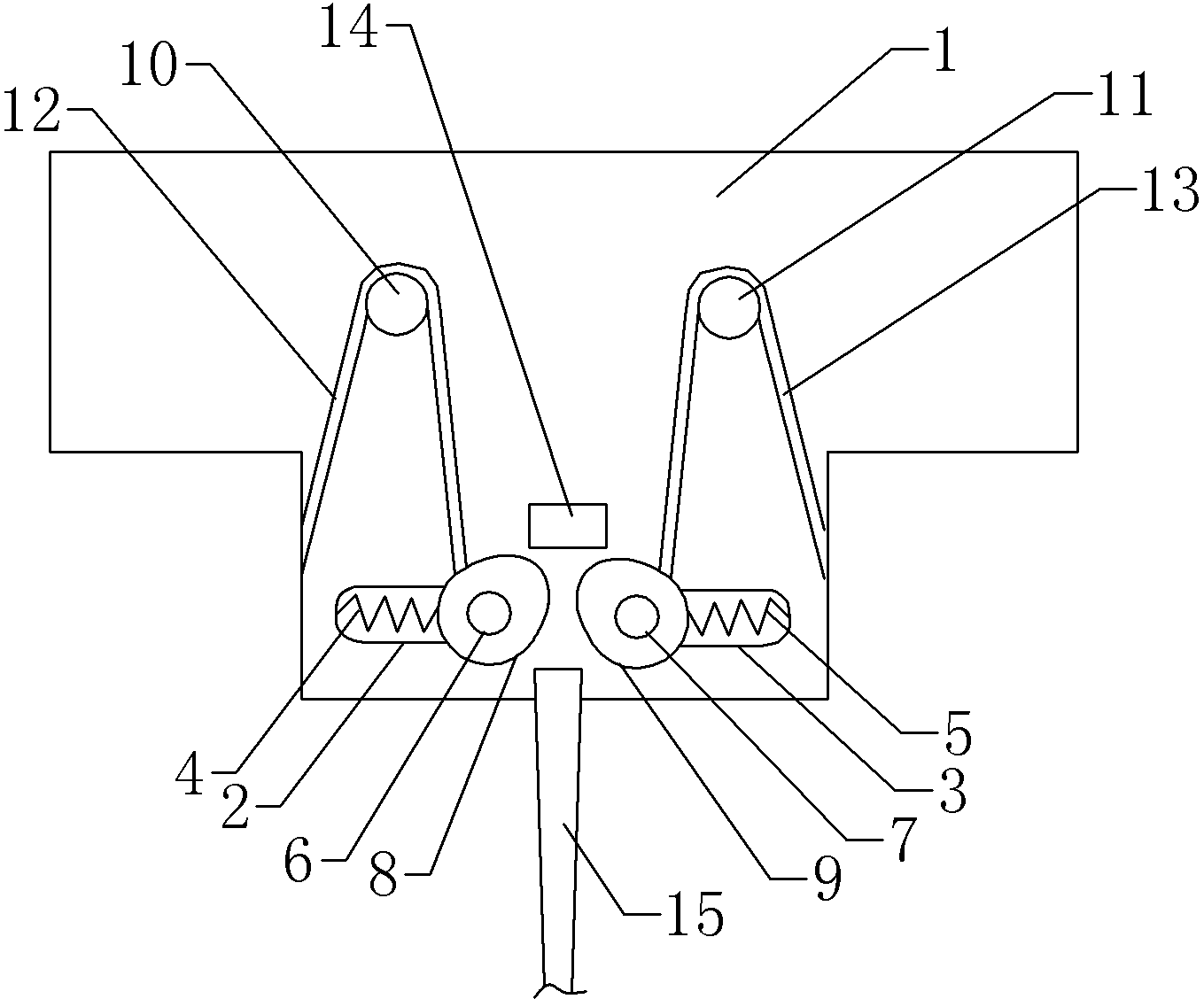
[0012] Such as figure 1 The shown positioning device for a shaft workpiece with a gradual cross section includes a base 1, a first slide hole 2, a second slide hole 3, a first compression spring 4, a second compression spring 5, a first support shaft 6, a second Two support shafts 7, the first roller 8, the second roller 9, the third support shaft 10, the fourth support shaft 11, the first torsion spring 12, the second torsion spring 13, the positioning stopper 14 and the gradual change interface shaft type workpiece 15 .

[0013] The first sliding hole 2 and the second sliding hole 3 are all arranged on the base 1, the long diameters of the first sliding hole 2 and the second sliding hole 3 are on a straight line, and the first sliding hole 2 and the second sliding hole 3 The first support shaft 6 and the second support shaft 7 that can ...


PUM


Abstract

The invention provides a positioning device for a shaft workpiece with a gradient section, which can clamp and position the workpiece stably. The device comprises a base, wherein a positioning structure used for clamping and positioning the shaft workpiece with the gradient section is arranged on the base; the positioning structure comprises a first sliding hole and a second sliding hole formed in the base; the long diameters of the first sliding hole and the second sliding hole are in a straight line; a first supporting shaft and a second supporting shaft which can move along the sliding holes are respectively arranged in the first sliding hole and the second sliding hole; a first roller and a second roller respectively sleeve the first supporting shaft and the second supporting shaft; a clamping part of the shaft workpiece with the gradient section is formed between the first roller and the second roller; a first pressure spring, a second pressure spring and a positioning stop block are also arranged on the base; the first pressure spring is supported between one side, back on to the second roller, of the first roller and the side wall of the first sliding hole; the second pressure spring is supported between one side, back on to the first roller, of the second roller and the side wall of the second sliding hole; the positioning stop block is arranged in the side direction of the clamping part.

Description

technical field [0001] The invention relates to a fixture, in particular to a positioning device for shaft workpieces with gradual cross-sections. Background technique [0002] A shaft is a mechanical part that supports and revolves with a rotating part to transmit motion, torque or bending moment. According to the bearing capacity of the shaft, the shaft is divided into a core shaft, a transmission shaft and a rotating shaft. Among them, the mandrel is used to support the rotating parts, which only bears the bending moment and does not transmit the torque. Therefore, in order to save material and reduce the weight of the mandrel itself, when the bending moments borne by each part of the mandrel are quite different, the variable-section shaft is usually used. The shaft with variable section adopts a larger section where the bending moment is larger and a smaller section where the bending moment is smaller. In some cases, if the cross-section of the adjacent part of the ...

Claims


Application Information

Patent Timeline
IPC IPC(8): B23Q3/06
CPCB23Q3/064
Inventor 王学军
Owner CHONGQING HANGFEI MACHINERY MFG
Learn More