Flaring and stamping device with positioning structure

A technology of flaring stamping and positioning structure, which is applied in the direction of positioning device, feeding device, storage device, etc. It can solve the problems of low efficiency of product clamping by operators, limited positioning accuracy, and low expansion efficiency, etc., and achieves practicability Good, strong applicability and convenient operation

Active Publication Date: 2019-09-06
上海航空发动机制造有限公司
View PDF7 Cites 4 Cited by
  • Summary
  • Abstract
  • Description
  • Claims
  • Application Information

AI Technical Summary

Problems solved by technology

[0003] In the prior art, during the production process of automobile shock absorbers, due to the relatively limited positioning accuracy, not only the expansion efficiency is low, the quality is poor, but also the operator's clamping efficiency of the product is low.

Method used


Image

  • Flaring and stamping device with positioning structure

Examples


Embodiment 1)

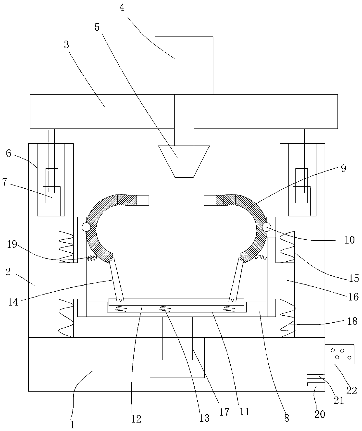
[0017] figure 1 A specific embodiment of the invention is shown in which figure 1 It is a structural schematic diagram of the present invention.

[0018] See figure 1 , a flaring stamping device with a positioning structure, comprising a base 1, two vertical support plates 2 arranged on the base, a horizontal plate 3 is arranged on the top of the vertical support plate, and a horizontal plate 3 is arranged on the horizontal A driving motor 4 is arranged on the plate, a flared rod 5 connected to the main shaft of the driving motor is fixed in the middle of the bottom surface of the transverse plate, and a lifting cavity 6 is arranged on the top surface of the vertical supporting plate. A lifting cylinder 7 is fixed on the bottom wall of the lifting cavity, and the piston shaft of the lifting cylinder is fixed at both ends of the bottom surface of the transverse plate, and the bottom of the two vertical support plates is provided with a The bearing plate 8 is provided with tw...


PUM


Abstract

The invention discloses a flaring and stamping device with a positioning structure. The device comprises a base and two vertical supporting plates arranged on the base, a transverse plate is arrangedat the tops of the vertical supporting plates, a driving motor is arranged on the transverse plate, and a flaring rod connected with a main shaft of the driving motor is fixed to the middle of the bottom surface of the transverse plate. The flaring and stamping device is characterized in that lifting cavities are formed in the top surfaces of the vertical supporting plates correspondingly; liftingcylinders are fixed to the bottom walls of the lifting cavities correspondingly; piston shafts of the lifting cylinders are fixed to the two ends of the bottom surface of the transverse plate correspondingly; a load-bearing plate is arranged between the lower portions of the two vertical supporting plates; two C-shaped positioning warping rods are arranged on the load-bearing plate; a cavity is formed in the center of the top surface of the load-bearing plate; an abutting panel is arranged in the cavity; and buffering springs are fixed between the abutting panel and the bottom wall of the cavity. The flaring and stamping device is reasonable in structure arrangement, the flaring stability and reliability can be guaranteed easily, position deviation can be prevented, the flaring precisioncan be improved easily, the applicability is high, and the practicability is good.

Description

technical field [0001] The invention belongs to the technical field of flaring processing equipment, and in particular relates to a flaring stamping device with a positioning structure. Background technique [0002] In order to quickly attenuate the vibration of the frame and body and improve the ride comfort and comfort of the car, the suspension system of the car is generally equipped with a shock absorber, and the two-way acting barrel shock absorber is widely used in the car. [0003] In the prior art, during the production process of the automobile shock absorber, due to the relatively limited positioning accuracy when flaring the shock absorber, not only the flaring efficiency is low, the quality is poor, but also the operator's clamping efficiency of the product is low. Contents of the invention [0004] The object of the present invention is to provide a flaring stamping device with a positioning structure, which has a reasonable structure and strong applicability....

Claims


Application Information

Patent Timeline
Patent Type & Authority Applications(China)
IPC IPC(8): B21D43/00B21D31/04B21D53/88
CPCB21D31/04B21D43/003B21D53/88
Inventor 叶晓丹
Owner 上海航空发动机制造有限公司
Why Eureka
Try Eureka