Inclined disc tool magazine

A disc cutter and tilting technology, which is applied in the field of machine tool magazines, can solve the problems of heavy tool magazine weight, potential safety hazards, and time-wasting, and achieve the effects of good tool change, weight reduction, and production cost reduction

Pending Publication Date: 2018-02-16
TIANJIN ZHONGDA PRECISION MACHINERY
0 Cites 4 Cited by

AI-Extracted Technical Summary

Problems solved by technology

[0002] Machine tool is a common processing equipment, and with the improvement of production automation, automatic tool change of machine tools has been realized on most machine tools, which is one of the better ways to improve processing efficiency and save processing costs. Existing machine tools In the equipment, the fixing method and the structure...

Method used

Principle of work of the present invention: a kind of tilting type disc tool storehouse as shown in Figure 1, by bolt 102, U-shaped frame 101 is fixed on the column, guarantees that the buffer block 106 of bottom contacts with workbench, and rubber spring 105 is in a compressed state, the other end of the base 1 is placed in the slide rail 202 through the guide block 110, and after being adjusted to a suitable position, it is fixed through the positioning hole 201 by a screw, and checks whether there is any problem with the corresponding connection part of the upper part of the bracket 2, so as to ensure that Good support force, the tool magazine 4 is welded with the support 2 at a certain inclination angle, and further disperses the support force through the sub-support 206 and the stabilizer bar 208 to improve the stability of the support. As shown in Figure 1, the tool magazine 3 is oblique 25 degrees of inclination to ensure that it is parallel to the axis of the tool 4 in use, check whether the clamping device 304 in the tool magazine 3 can work normally, clamp the tool 4 to the corresponding circular groove 303, and pass the hydraulic cylinder 3043 Control the lowering of the fixed block 3046, push the slide block 3047 matched with its inclined surface to move to the left and right sides, and then drive the clamping rods 3049 on it to move away from each other. After reaching the maximum position, put the cutter 4 into the circular groove 303, hydraulic cylinder 3043 Reverse movement, the spring 3048 resets accordingly, and the clamping rods 3049 are close to each other, thereby realizing the clamping and positioning of the tool 4. When changing the tool, align the used tool 4 with the vacant circular groove 303, and the hydraulic cylinder 3043 Drive the two clamping rods 3049 away from each other, lower them and place them in the circular groove 303, the hydraulic cylinder 3043 moves in the opposite direction, and the clamping block 3040 clamps it, and the main shaft rises, that is, the tool 4 is unloaded and moved to the corresponding replacement Above the position of the tool 4, the tool can be changed through the same operation.
Wherein, a plurality of sub-supports 206 are distributed into an umbrella-like structure along the axial center circumference of the fixed shaft 205, the axis of the fixed shaft 205 coincides with the axis of the center seat 305, and the fixed mount 203 The four corners of the frame are all fixedly connected to the sub-bracket 206 through stabilizing rods 208, the stabilizing rods 208 are in a state of spreading outwards, and the included angle between the upper end surface of the fixing frame 203 and the axis of the fixing shaft 205 is 70 Between -75 degrees, the center seat 305 and the fixed shaft 205 are formed by welding. The design of the umbrella structure increases the force-bearing area through the scattered connection form, reduces the local gravity, and avoids the breakage of the connection. The stability of the support ensures that the axis of the center seat 305 is parallel to the axis of the overall situation in use during the tool change process, which increases the accuracy of tool change and improves the efficiency of tool change.
Wherein, between a plurality of said knife rests 301 of circumferential distribution, connect in series by annular rod 302, between each said knife rest 301 and said center seat 305, be fixedly connected by strut 306, said strut 306 are placed on both sides of each clamping device 304 respectively. The structure of this fixed form is simple, and the weight of the tool magazine 3 can be reduced to the greatest extent on the basis of achieving the same stability, and the stability effect of the tool magazine 3 can be improved without affecting the normal operation of tool changing.
Wherein, described base 1 comprises the U-shaped frame 101 that is fixed on the column side by bolt 102, and the other end curved column 104 of described U-shaped frame 101 connects seat plate 109, and the other end of described seat plate 109 passes guide The block 110 is placed in the slide rail 202, the screw passes through the positioning hole 201 to fix it on the bracket 2, and the bottom of the curved column 104 is provided with a reinforcing rib 103 near the end of the U-shaped frame 101, A buffer mechanism is provided at the end of the bottom of the bent column 104 away from the U-shaped frame 101 . The structure design of this base 1 is convenient to be fixed on the column, and the stability after fixing is high, and it is not easy to shift. The positioning accuracy is high, the design of the reinforcing rib 103 prevents the deformation of the longer curved column 104, improves the stability of the fixed force, further disperses the local pressure through the design of the buffer mechanism, and increases the balance of the force, and the middle part is not easy Fracture occurs, more durable.
Wherein, described buffer mechanism comprises first buffer plate 108 and second buffer plate 107, is connected by guide rod 112 between described first buffer plate 108 and described second buffer plate 107, passes through described guide The rod 112 is provided with a rubber spring 105 , the guide rod 112 at the bottom of the second buffer plate 107 is connected by a nut 111 , and the bottom of the second buffer plate 107 is provided with a plurality of buffe...

Abstract

The invention provides an inclined disc tool magazine. The tool magazine comprises a tool magazine body; a support is welded at the bottom of the tool magazine body and is connected with a base; the tool magazine body comprises a central seat and tool rests; circular grooves are formed in the tool rests; tools are arranged in the circular grooves; clamping devices corresponding to all the circulargrooves are arranged on the central seat; two symmetric clamping rods of each clamping device are arranged on two sides of each circular groove, and ends, close to each other, of the clamping rods are arranged on the central seat through a rotating shaft; springs are arranged between the central seat and the tool rests; and symmetric sliding blocks are arranged between the springs and the centralseat. The inclined disc tool magazine is simple in structure and has the better tool changing effect on the machining tool having the certain inclination angle, the tool changing process is smooth, the stability is better, the precision is higher, the tools in the tool magazine are not prone to loosening, tool changing in the inclined state can be realized conveniently and quickly, the tool changing efficiency is improved, and the production cost is reduced.

Application Domain

Positioning apparatusMetal-working holders +1

Technology Topic

EngineeringMachine tool +2

Image

  • Inclined disc tool magazine
  • Inclined disc tool magazine
  • Inclined disc tool magazine

Examples

  • Experimental program(1)

Example Embodiment

[0035] It should be noted that the embodiments of the present invention and the features of the embodiments may be combined with each other under the condition of no conflict.
[0036] In the description of the present invention, it should be understood that the terms "center", "portrait", "horizontal", "top", "bottom", "front", "rear", "left", "right", " The orientation or positional relationship indicated by vertical, horizontal, top, bottom, inner, outer, etc. is based on the orientation or positional relationship shown in the drawings, and is only for the convenience of describing the present invention and The description is simplified rather than indicating or implying that the device or element referred to must have a particular orientation, be constructed and operate in a particular orientation, and therefore should not be construed as limiting the invention. In addition, the terms "first", "second", etc. are used for descriptive purposes only, and should not be construed as indicating or implying relative importance or implying the number of indicated technical features. Thus, a feature defined as "first", "second", etc., may expressly or implicitly include one or more of that feature. In the description of the present invention, unless otherwise specified, "plurality" means two or more.
[0037] In the description of the present invention, it should be noted that the terms "installed", "connected" and "connected" should be understood in a broad sense, unless otherwise expressly specified and limited, for example, it may be a fixed connection or a detachable connection Connection, or integral connection; can be mechanical connection, can also be electrical connection; can be directly connected, can also be indirectly connected through an intermediate medium, can be internal communication between two elements. For those of ordinary skill in the art, the specific meanings of the above terms in the present invention can be understood through specific situations.
[0038] The present invention will be described in detail below with reference to the accompanying drawings and in conjunction with the embodiments.
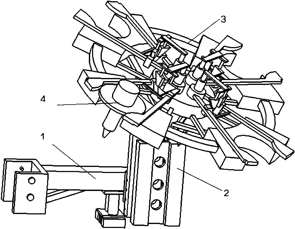
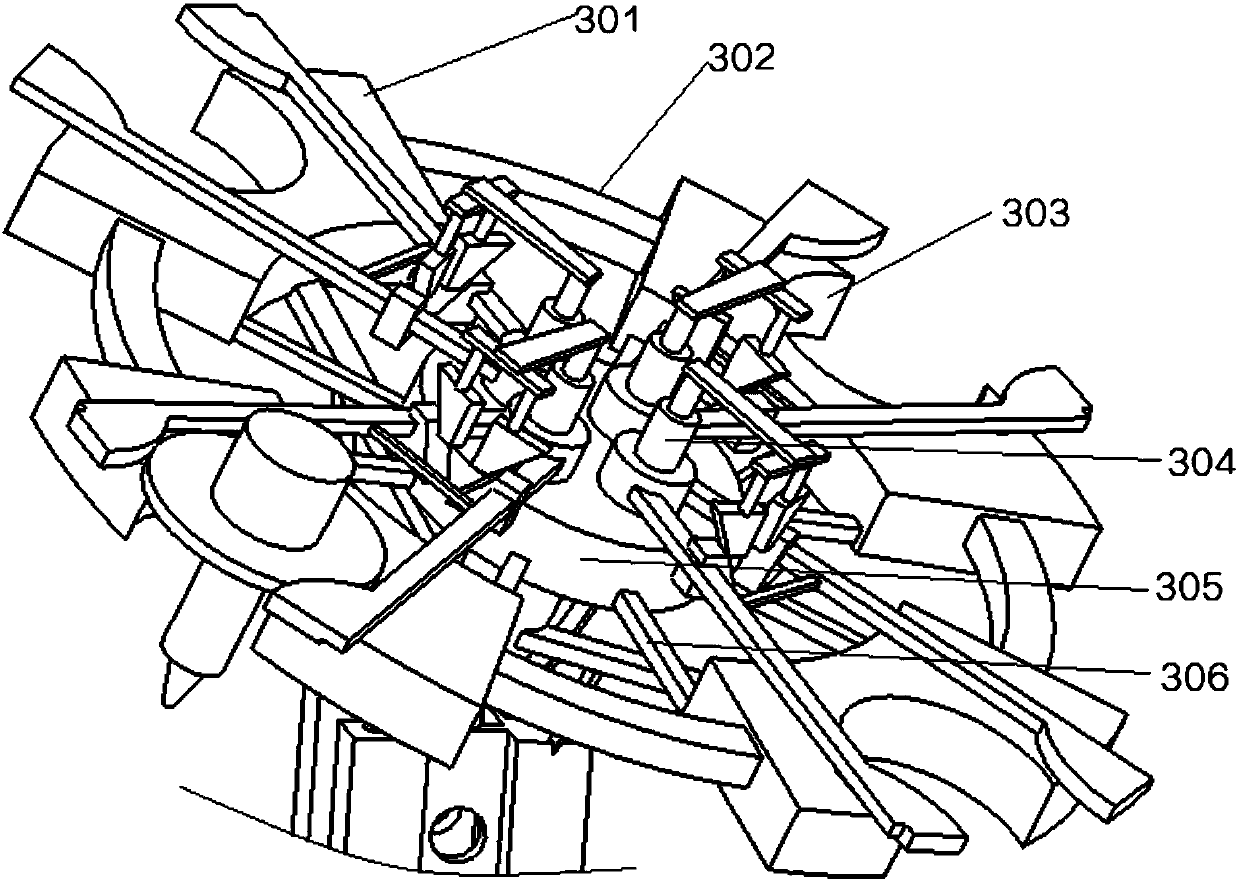
[0039] like figure 1 An inclined disc tool magazine shown in the figure includes a tool magazine 3, a bracket 2 is welded at the bottom of the tool magazine 3, and a base 1 is detachably connected to one end of the bracket 2 away from the tool magazine 3. 3 includes a center seat 305 and a plurality of tool holders 301 distributed around its circumference. The tool holder 301 is provided with a circular groove 303, and the tool 4 is placed in the circular groove 303. The center seat 305 corresponds to each Each of the circular grooves 303 is further provided with a clamping device 304. Two symmetrical clamping rods 3049 of the clamping device 304 are placed on both sides of the circular groove 303, and the clamping rods 3049 are V-shaped. A zigzag structure, the ends of which are close to each other are placed on the center seat 305 through a rotating shaft 3044, and a spring 3048 is provided between the two clamping rods 3049 at the position between the center seat 305 and the tool holder 301 , the two clamping rods 3049 between the spring 3048 and the center seat 305 are provided with symmetrical sliding blocks 3047, the sliding blocks 3047 are driven to slide by the fixed blocks 3046 matched with them, and push the two The clamping rods 3049 are close to or away from each other. Overcoming the shortcomings of the prior art, the structure is simple, the tool changing effect of the machine tool with a certain inclination angle is better, the tool changing process is smooth, the stability is good, the tool changing position can be accurately identified, the accuracy is high, and the tool magazine The tool 4 in 3 is not easy to loosen, which can conveniently and quickly realize tool change in an inclined state, improve tool change efficiency, save processing time, and reduce production cost.
[0040] A plurality of the tool holders 301 distributed around the circumference are connected in series by an annular rod 302, and each of the tool holders 301 and the center seat 305 is fixedly connected by a support rod 306, and the support rods 306 are respectively arranged on both sides of each of the clamping devices 304 . This fixed form has a simple structure, can reduce the weight of the tool magazine 3 to the greatest extent on the basis of achieving the same stability, and improve the stability of the tool magazine 3 without affecting the normal operation of the tool change.
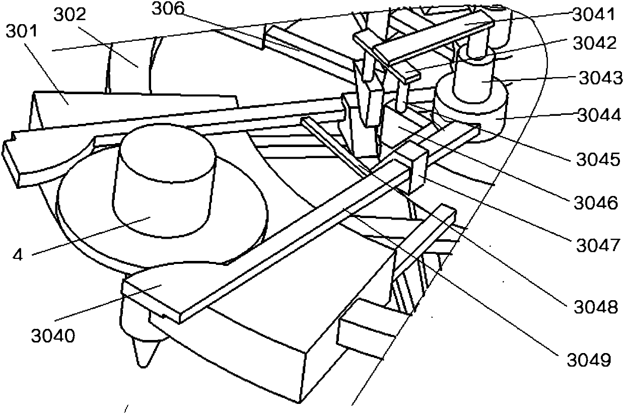
[0041] Wherein, two symmetrical clamping rods 3049 are rotatably connected to the rotating shaft 3044, a hydraulic cylinder 3043 is arranged on the rotating shaft 3044, and a fixing plate 3041 is fixed on the top rod of the hydraulic cylinder 3043, and the fixing plate 3041 is provided with a top plate 3042 protruding toward the end of the tool holder 301, the bottom of the top plate 3042 is provided with symmetrical fixing columns 3045, the other end of each of the fixing columns 3045 is fixed to the fixing block 3046, the The mating surface of the fixing block 3046 and the sliding block 3047 is an inclined inclined surface. This kind of clamping device 304 has a simple structure and a good clamping effect. The two clamping rods 3049 are pushed closer to or away from each other through the cooperation of the inclined fixing block 3046 and the sliding block 3047, so as to be placed opposite to each other in the circular groove 303. The tool 4 is positioned and clamped, and will not fall off due to its inclined surface. During the tool changing process, in conjunction with the tool changing step, an auxiliary clamping force can also be applied to the tool 4 to be replaced, making it easy to fall off. , to improve the tool change efficiency of the tool change accuracy.
[0042] The end of the clamping rod 3049 away from the rotating shaft 3044 is provided with a clamping block 3040. The clamping block 3040 has a semicircular structure, and its semicircular part is in contact with the edge of the cutter 4. Two The distance between the clamping blocks 3040 is greater than the maximum diameter of the tool 4, the elongation of the spring 3048 is greater than the sum of the displacements of the two clamping rods 3049, the fixed block 3046 and the sliding The distance between the semicircular edges of the two clamping blocks 3040 under the maximum stroke of the block 3047 is greater than the maximum diameter of the tool 4 , and the axis of rotation of the two clamping rods 3049 is parallel to the axis of the center seat 305 . The setting of the clamping block 3040 improves the clamping force on the tool 4, so that it is not easy to fall on the inclined surface, and has better stability, and through the design of the relative size, it is ensured that the tool 4 can be realized within the pulling force range of the spring 3048. Then, the spring 3048 is gradually reset by the distance between the fixed block 3046 and the slider 3047, so as to realize the slow clamping of the tool 4 without damaging the tool 4, and realize the fast and high-precision realization of the tool 4. Replace and clamp.
[0043] The bracket 2 includes a fixed shaft 205 placed at the bottom of the center seat 305 , and a plurality of sub-brackets 206 protruding from the side wall of the fixed shaft 205 are respectively fixedly connected to the bottom of the tool rest 301 , and the fixed shaft 205 The other end is welded with a positioning seat 207, the bottom of the positioning seat 207 is connected with the fixing frame 203 through the triangular bracket 204, the fixing frame 203 is a cylindrical structure, and each side thereof is provided with a groove 210, and its interior is the cavity 209 . This kind of bracket 2 has a simple structure and can reduce the mass to the greatest extent. While reducing the weight, through the cooperative connection between the sub-bracket 206 and the triangular bracket 204, the stability of the support is improved, and the connection is easy to occur in the presence of a certain angle. In the case of fracture, the service life of the bracket 2 is improved.
[0044] A plurality of the sub-brackets 206 are distributed in an umbrella-shaped structure along the axis of the fixed shaft 205 , the axis of the fixed shaft 205 coincides with the axis of the center seat 305 , and the four corners of the fixed frame 203 Both are fixedly connected to the sub-bracket 206 through a stabilizer bar 208, the stabilizer bar 208 is in an outwardly dispersed state, and the angle between the upper end surface of the fixing frame 203 and the axis of the fixing shaft 205 is 70-75 degrees In between, the center seat 305 and the fixed shaft 205 are formed by welding. The design of the umbrella-shaped structure increases the force-bearing area through the scattered connection form, reduces the local gravity bearing, and avoids the breakage of the connection. The stability of the support ensures that the axis of the center seat 305 is parallel to the axis of the overall situation in use during the tool changing process, which increases the accuracy of the tool changing and thus improves the tool changing efficiency.
[0045] Wherein, the recessed inner wall of each groove 210 is provided with a plurality of vertically evenly distributed through holes 211, and the symmetrical two ends of one side of the fixing frame 203 that are not recessed are provided with sliding rails 202, corresponding to The two side walls of the slide rail 202 are respectively provided with a plurality of evenly distributed positioning holes 201 , and the axis of the positioning holes 201 is perpendicular to the center line of the fixing frame 203 . The arrangement of the groove 210 and the through hole 211 further reduces the weight of the bracket 2, and at the same time does not affect the overall stability, the supporting force is large, and the design of the slide rail 202 and the positioning hole 201 facilitates its fixation on the machine tool and the positioning accuracy. It is relatively high, and the relative distance can be adjusted vertically according to different situations. It can adapt to a wider range and has strong practicability.
[0046] Wherein, the base 1 includes a U-shaped frame 101 fixed on the side of the column by bolts 102 , the other end of the U-shaped frame 101 is connected to the seat plate 109 by a curved column 104 , and the other end of the seat plate 109 is placed through the guide block 110 In the slide rail 202, screws pass through the positioning holes 201 to fix it on the bracket 2, and a reinforcing rib 103 is provided at the bottom of the bent column 104 near the U-shaped frame 101. A buffer mechanism is provided at one end of the bottom of the column 104 away from the U-shaped frame 101 . The design of the structure of the base 1 is easy to fix on the upright column, and the stability after fixing is high, and it is not easy to be offset. The positioning accuracy is high, the design of the reinforcing ribs 103 prevents the deformation of the long bending column 104, improves the stability of the fixed force, and further disperses the local pressure through the design of the buffer mechanism to increase the balance of the force, and the middle part is not easy to Broken, more durable.
[0047]The buffer mechanism includes a first buffer plate 108 and a second buffer plate 107 . The first buffer plate 108 and the second buffer plate 107 are connected by a guide rod 112 . There is a rubber spring 105, the guide rod 112 at the bottom of the second buffer plate 107 is connected by a nut 111, and the bottom of the second buffer plate 107 is provided with a plurality of buffer blocks 106 arranged at intervals. This kind of buffer mechanism is simple in structure and relatively dispersed in force, which can easily and quickly disperse and buffer the relatively large force received by the bending column 104 , with good buffering effect and prolonging the service life of the base 1 .
[0048] The axis of the guide rod 112 is parallel to the symmetry centers of the two guide blocks 110 , and the height of the buffer block 106 is greater than the length of the guide rod 112 extending from the second buffer plate 107 . It is ensured that the buffer block 106 and the work surface can be contacted and pressed, so that the rubber spring 105 is pressed to provide up and down supporting force for the bent column 104. The more dispersed the buffer blocks 106 are, the more uniform the force is.
[0049] The working principle of the present invention: as figure 1 In the shown inclined disc tool magazine, the U-shaped frame 101 is fixed on the column by the bolt 102 to ensure that the buffer block 106 at the bottom is in contact with the worktable, and the rubber spring 105 is in a compressed state, and the other end of the base 1 passes through the guide. The block 110 is placed in the slide rail 202, and after being adjusted to a suitable position, it is fixed by screws through the positioning holes 201. Check whether there is any problem with the corresponding connection part of the upper part of the bracket 2 to ensure a better supporting force. The tool magazine 4 is at a certain inclination angle. It is welded with the bracket 2, and the supporting force is further dispersed through the sub-bracket 206 and the stabilizer bar 208 to improve the stability of the support, such as figure 1 As shown, the tool magazine 3 is inclined downward by 25 degrees to ensure that it is parallel to the axis of the tool 4 in use. Check whether the clamping device 304 in the tool magazine 3 can work normally, and clamp the tool 4 to the corresponding The circular groove 303 controls the lowering of the fixed block 3046 through the hydraulic cylinder 3043, and pushes the slider 3047 matched with its inclined surface to move to the left and right sides, thereby driving the clamping rods 3049 on it to move away from each other. To the circular groove 303, the hydraulic cylinder 3043 moves in the opposite direction, the spring 3048 is reset accordingly, and the clamping rods 3049 approach each other, thereby realizing the clamping and positioning of the tool 4. The groove 303 is aligned, the hydraulic cylinder 3043 drives the two clamping rods 3049 away from each other, and is lowered into the circular groove 303. The hydraulic cylinder 3043 moves in the opposite direction, and the clamping block 3040 clamps it. Lower the tool 4, move it to the position above the corresponding replacement tool 4, and change the tool through the same operation.
[0050] The above descriptions are only preferred embodiments of the present invention, and are not intended to limit the present invention. Any modifications, equivalent replacements, improvements, etc. made within the spirit and principles of the present invention shall be included in the scope of the present invention. within the scope of protection.

PUM

no PUM

Description & Claims & Application Information

We can also present the details of the Description, Claims and Application information to help users get a comprehensive understanding of the technical details of the patent, such as background art, summary of invention, brief description of drawings, description of embodiments, and other original content. On the other hand, users can also determine the specific scope of protection of the technology through the list of claims; as well as understand the changes in the life cycle of the technology with the presentation of the patent timeline. Login to view more.

Similar technology patents

Body condition measuring device

InactiveUS20050234351A1simple structure
Owner:DENSO CORP

Magnetic cooling apparatus and control method thereof

ActiveUS20130180263A1simple structure
Owner:SAMSUNG ELECTRONICS CO LTD

Dual-Drivetrain of Power-Assist Vehicle

InactiveUS20100181130A1enhance uphill momentumsimple structure
Owner:CHOU WEN CHENG

Classification and recommendation of technical efficacy words

  • Simple structure

Sharing system for air-conditioning coat

InactiveCN107440179ASimple structureeasy to wear
Owner:QINGDAO HAIER AIR CONDITIONER GENERAL CORP LTD

Feeding device of sorter of batteries plate

InactiveCN101357717ASimple structurecooperate well
Owner:NANJING NORMAL UNIVERSITY

Emergency parachuting device and method for multiple-rotor unmanned aerial vehicle

InactiveCN103895870Aavoid aircraft crashSimple structure
Owner:SOUTH CHINA AGRI UNIV +1
Why Eureka
Try Eureka