Non-magnetic sheet clamping and positioning tool and manufacturing method thereof

A technology for clamping and positioning and manufacturing methods, which is applied to positioning devices, clamping, manufacturing tools, etc., can solve the problems of non-magnetic thin plates that cannot be clamped and positioned, and achieve the effects of simple structure, easy operation, and convenient processing

Inactive Publication Date: 2014-08-06
NO 43 INST OF CHINA ELECTRONICS TECH GRP CETC
View PDF9 Cites 3 Cited by
  • Summary
  • Abstract
  • Description
  • Claims
  • Application Information

AI Technical Summary

Problems solved by technology

[0003] One of the objectives of the present invention is to provide a non-magnetic thin plate clamping and positioning tool, which overcomes the defect that the traditional tooling cannot clamp and position the non-magnetic thin plate

Method used


Image

  • Non-magnetic sheet clamping and positioning tool and manufacturing method thereof
  • Non-magnetic sheet clamping and positioning tool and manufacturing method thereof
  • Non-magnetic sheet clamping and positioning tool and manufacturing method thereof

Examples


Embodiment Construction

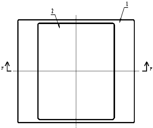
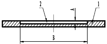
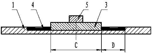
[0023] image 3 The shown non-magnetic thin plate clamping and positioning tool includes a base plate 1 and a plate material 3. A groove 2 is opened on the base plate 1, and the plate material 3 is placed in the groove 2. Between the edge of the plate material 3 and the inner wall of the groove 2 A gap area is provided, and the alloy material filling layer 4 is filled in the gap area, and a counterweight 5 is pressed on the side of the plate 3 away from the bottom surface of the groove 2 .

[0024] Preferably, the above-mentioned alloy material used as the alloy material filling layer 4 is tin-bismuth alloy, and the mass fraction of bismuth element in the tin-bismuth alloy is 58%. The base plate 1 is made of magnetic steel, which can meet the installation requirements of magnetic workbenches such as grinding machines, milling machines, and machining centers, and can also meet the installation requirements of traditional non-magnetic workbenches, which is convenient to use.

...


PUM


Abstract

The invention provides a non-magnetic sheet clamping and positioning tool and a manufacturing method thereof and relates to the field of machining of machinery, electrons, materials and the like. The non-magnetic sheet clamping and positioning tool comprises a base plate and a board, wherein a groove is formed in the base plate, the board is placed in the groove, a gap region is arranged between the edge of the board and the inner wall of the groove and full of an alloy material filling layer. The manufacturing method comprises the steps of heating the base plate; placing solid bismuth-tin alloy in the groove; placing the board in the groove to enable the bottom face of the board to adhere to the bottom face of the groove after the bismuth-tin alloy is molten; cooling the base plate, enabling the bismuth-tin alloy to be solidified and filling the bismuth-tin alloy in the gap region between the edge of the board and the inner wall of the groove; taking down a balancing weight. The combined effects of the steel base plate provided with the groove and the bismuth-tin alloy are utilized to achieve the board locking and clamping purpose. The non-magnetic sheet clamping and positioning tool is simple in structure and convenient to machine, suitable for large and thin plate parts with large surfaces required to be machined and especially suitable for machining of non-magnetic materials.

Description

technical field [0001] The invention relates to the processing fields of machinery, electronics, materials, etc., in particular to a non-magnetic sheet clamping and positioning tool and a manufacturing method thereof. Background technique [0002] In the processing fields of machinery, electronics, materials and other industries, such as milling, grinding and other occasions, it is necessary to use tooling to clamp and fix the workpiece before starting the next step of processing. The traditional clamping method is mainly mechanical structure tooling, mainly vise, vise, splint and other tools. Mechanical structure tooling can complete the processing and positioning requirements of ordinary parts, but if it is a large and thin non-magnetic plate part that needs to grind its large surface, it will not be able to achieve the purpose of workpiece clamping. For example, when grinding two large surfaces of a large and thin non-magnetic plate, the magnetic workbench of the grinder...

Claims


Application Information

Patent Timeline
Patent Type & Authority Applications(China)
IPC IPC(8): B23Q3/06B24B41/06B23P15/00
CPCB23Q3/062B23P15/00B24B41/068
Inventor 赵飞张崎史常东杨磊程海东冯东张玉君
Owner NO 43 INST OF CHINA ELECTRONICS TECH GRP CETC
Why Eureka
Try Eureka