

Circumference indexing scribing compass
An indexing and gauge technology, applied in metal processing mechanical parts, precision positioning equipment, metal processing equipment, etc., can solve the problems of high cost of indexing tools, cumbersome operation, poor accuracy, etc., to achieve simple use, accurate adjustment, Efficient indexing effect
- Summary
- Abstract
- Description
- Claims
- Application Information
AI Technical Summary
Problems solved by technology
Method used
Image


Examples
Embodiment 1
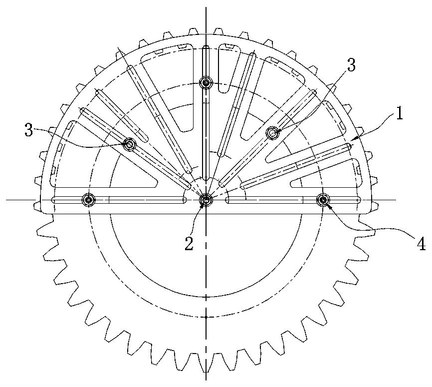
[0030] Such as image 3 As shown, the diameter of the inner hole of the part is Φ340mm, the diameter of the required indexing circle is Φ410mm, the positioning diameter of the positioning pin 3 is 10mm, the measuring diameter is 20mm, the radial length or diameter of the indexing slider 4 and the fixing pin 2 are both 10mm, Use a vernier caliper to measure the distance D1 between the two positioning pins 3 and the fixed pin 2. Considering that the positioning pin 3 and the fixed pin 2 have a certain size, in order to ensure that the two positioning pins 3 are tangent to the inner hole of the part, the planning The center of rotation of the device body 1 (that is, the center of the fixing pin 2) coincides with the center of the part. D1 should satisfy: D1 = 170 (radius of the inner hole of the part) + 10 (radius of the fixing pin + radius of the positioning pin) = 180mm, and then Utilize the vernier caliper to measure the distance D2 between the indexing slider 4 and the fixed ...
Embodiment 2
[0034] Such as Figure 4As shown, the diameter of the outer circle of the part is Φ500mm, the required indexing circle diameter is Φ410mm, the positioning diameter of the positioning pin 3 is 10mm, the measuring diameter is 20mm, the radial length or diameter of the indexing slider 4 and the fixing pin 2 are both 10mm, Use a vernier caliper to measure the distance D1 between the two positioning pins 3 and the fixed pin 2 respectively. Therefore, in order to ensure that the two positioning pins 3 are tangent to the outer circle of the part, the center of rotation of the planer body 1 (that is, the center of the fixed pin 2) and The center of the part coincides, D1 should satisfy: D1=250 (radius of the outer circle of the part) + 20 (radius of the fixed pin + positioning radius of the positioning pin + measuring radius of the positioning pin) = 270mm, and then use the vernier caliper to measure the indexing slider 4 and the fixed The distance D2 between the pins 2 also considers...
Embodiment 3
[0043] Such as Figure 6 As shown, the diameter of the inner hole of the part is Φ500 mm, the fixed pin 2 is on the circle centered on the center of the planer body and the radius is 400 mm, the required graduation circle diameter is Φ600 mm, and the positioning pin 3 has a positioning diameter of 10 mm. The diameter is 20mm, and the radial length or diameter of the indexing slider 4 and the fixed pin 2 is 10mm. Use a vernier caliper to measure the distance D1 between the two positioning pins 3 and the fixed pin 2. Considering the positioning pin 3 and the fixed pin 2 It has a certain size, so in order to ensure that the center of rotation of the planer body 1 coincides with the center of the part when the two positioning pins 3 are tangent to the inner hole of the part, D1 should satisfy: D1=400 (the radius of the circle where the fixed pin is located)-250 ( Part inner hole radius) + 20 (fixed pin radius + positioning pin positioning radius + positioning pin measuring radius)...
PUM
| Property | Measurement | Unit |
|---|---|---|
| Diameter | aaaaa | aaaaa |
Abstract
Description
Claims
Application Information