Rheostat

A varistor and resistance wire technology, applied in sliding contact resistors and other directions, can solve the problems of vibration, accompanying noise, and resistance wire easily broken, and achieve the effect of overcoming vibration and noise, solving easy breaking and simple structure.

Inactive Publication Date: 2015-03-04
泉州台商投资区阳福信息技术有限公司
View PDF3 Cites 3 Cited by
  • Summary
  • Abstract
  • Description
  • Claims
  • Application Information

AI Technical Summary

Problems solved by technology

[0002] The document with the patent number ZL2009201400472 (name: luminescent rheostat) discloses a rheostat, which has been widely used now, and the following shortcomings are found in use: 1. The resistance wire is easy to break
2. There is vibration
3. There is noise when vibrating

Method used


Image

  • Rheostat
  • Rheostat
  • Rheostat

Examples


Embodiment 1

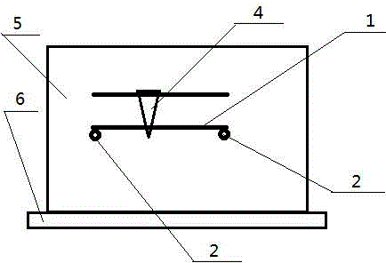
[0055] See attached figure 2 , is a structural representation of the present invention. A rheostat, comprising a panel 5, a resistance wire 1, a binding post 2 perpendicular to the panel and fixedly connected to the panel, a slide rail arranged parallel to the resistance wire, the slide rail and the panel are fixedly connected, and a slide for sliding along the slide rail 4. Both the slide rail and the resistance wire are electrically connected to the slider, and the characteristics are:

[0056]One end of the resistance wire 1 is fixedly connected to the terminal 2 and electrically connected;

[0057] The other end of the resistance wire 1 is in close contact with the binding post 2 that is matched with this end and is electrically connected with this end, and this end of the resistance wire is connected with an elastic spring that is used to pull the resistance wire and make the resistance wire receive tension. cable 3;

[0058] The other end of the elastic cable 3 is fi...

Embodiment 2

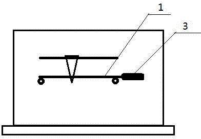
[0070] See attached image 3 , is a schematic diagram of the structure of this embodiment. A shock-absorbing rheostat, comprising a panel 5, a resistance wire 1, a binding post 2 perpendicular to the panel and fixedly connected to the panel, a slide rail arranged parallel to the resistance wire, the slide rail and the panel are fixedly connected, and are used for sliding along the slide rail Sliding piece 4, slide rail, resistance wire are all electrically connected with sliding piece, it is characterized in that:

[0071] One end of the resistance wire 1 is fixedly connected to the terminal 2 and electrically connected;

[0072] The other end of the resistance wire 1 is in close contact with the binding post 2 that is matched with this end and is electrically connected with this end, and this end of the resistance wire is connected with an elastic spring that is used to pull the resistance wire and make the resistance wire receive tension. cable 3;

[0073] The other end o...

Embodiment 3

[0080] In order to satisfy the following relationship between the terminal and the resistance wire: 1, close contact, 2, the elastic cable can well apply the tension to the resistance wire, the structure of the terminal is as follows: see the attached Figure 5 , the figure reflects the structural schematic diagram of the terminal. This figure is a front view. There is a central cylinder 21 perpendicular to the panel and one end fixedly connected to the panel. A cylinder 22 is sheathed outside the central cylinder 21, and both the central cylinder 21 and the cylinder 22 are made of conductors. In this way, the angle between the resistance wire and the elastic cable can be moderately increased so as not to cause the resistance wire not to be subjected to tension.


PUM


Abstract

The invention belongs to the field of rheostats. The rheostat in the prior art has the following defects: 1, resistance wires are easy to break; 2, vibration is generated; and 3, noise is generated along with vibration. The technical scheme adopted for solving the technical problems is as follows: the invention provides a rheostat which comprises a panel, resistance wires, binding posts, a sliding rail and a sliding vane, wherein the binding posts are vertical to the panel and are fixedly connected with the panel; the sliding rail is parallel to the resistance wires; the sliding rail is fixedly connected with the panel; the sliding vane is used for sliding along the sliding rail; and the sliding rail, the resistance wires and the sliding vane are electrically connected. The rheostat is characterized in that one end of each resistance wire is fixedly and electrically connected with one of the binding posts; the other end of each resistance wire is in tight contact with the binding post matched with the end and electrically connected with the end and is connected with an elastic cable for pulling the resistance wire to enable the resistance wire to get a tension; and the other end of each elastic cable is fixedly connected to the panel. The rheostat is simple in structure and is used for solving the problems of wire breaking, vibration, noise and the like.

Description

technical field [0001] The invention belongs to the field of sliding rheostats. Background technique [0002] The literature with the patent No. ZL2009201400472 (name: luminous varistor) discloses a varistor, which has been widely used now, and the following disadvantages are found in use: 1. The resistance wire is easy to break. 2. There is vibration. 3. There is noise when vibrating. Contents of the invention [0003] In order to solve the deficiencies of the prior art, the present invention discloses the following technical solutions, which solve the above-mentioned deficiencies, and the technical solutions adopted by the present invention to solve the technical problems are: [0004] A rheostat, comprising a panel, a resistance wire, a binding post perpendicular to the panel and fixedly connected to the panel, a slide rail arranged parallel to the resistance wire, the slide rail and the panel are fixedly connected, and a slide for sliding along the slide rail, the sl...

Claims


Application Information

Patent Timeline
Patent Type & Authority Applications(China)
IPC IPC(8): H01C10/44
Inventor 王振环
Owner 泉州台商投资区阳福信息技术有限公司
Why Eureka
Try Eureka