
Network diagram creation and management

A technology of power grid and grid voltage, applied in the field of power grid diagram construction and operation guidance, can solve problems such as indirect control delay

Active Publication Date: 2015-03-04
SMA SOLAR TECH AG
View PDF7 Cites 1 Cited by
  • Summary
  • Abstract
  • Description
  • Claims
  • Application Information

AI Technical Summary

Problems solved by technology

Furthermore, the indirect control of the unit by transferring a tariff profile to it is sluggish

Method used


Image

  • Network diagram creation and management
  • Network diagram creation and management
  • Network diagram creation and management

Examples


Embodiment Construction

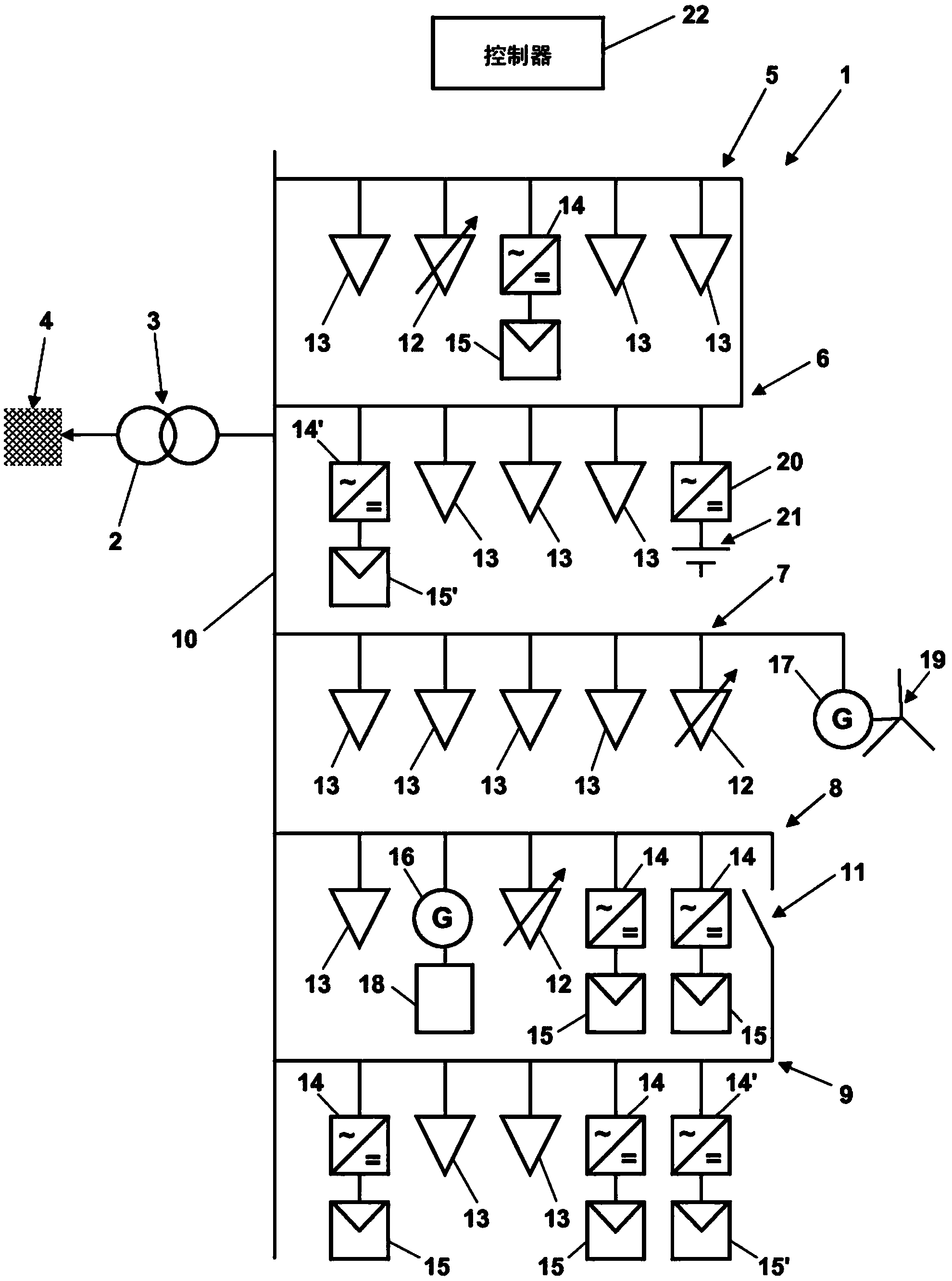
[0043] figure 1 A grid section 1 is schematically shown, which is connected via a transformer 2 at a grid connection point 3 to the remainder of the covered AC grid 4 and has an exemplary electrical topology, which is described further below. Network segment 1 is subdivided into various branches 5 to 9 , which originate from busbar 10 and can further branch in sub-branches not shown here. Here, the branches 5 and 6 are connected to one another at their ends and form a ring. The branch 7 ends open, while there is a switchable disconnection point 11 between the branches 8 and 9 . As long as no reactive power occurs in grid section 1 , a fixed grid nominal voltage of grid section 1 , which is specified by transformer 2 , is applied to busbar 10 . The branches 5 to 9 comprise (i) loads 12 and 13 which cannot be controlled in terms of their connected power as pure energy consumers and (ii) an inverter 14 with a connected photovoltaic generator 15 and Generators 16 and 17 with co...


PUM


Abstract

In order to determine the topology of a network section (1) of an alternating current network (4), said network section comprising a network connection point (3), at least one leg (5-9) that branches off from the network connection point (3) and has a plurality of energy consumption units (12, 13) and / or energy generation units (14 / 15; 16 / 18; 17 / 19; 20 / 21), and at least one measurement point in the at least one leg (5-9), variations of connection power values of at least one of the plurality of energy consumption units (12, 13) and / or energy generation units (14 / 15; 16 / 18;7 / 19; 20 / 21) and variations of the network voltage at the at least one measurement point of the network section (1) are measured. Then dependencies of the variations of the network voltage at the at least one measurement point on the variations of the connection power values of at least some individual energy consumption units and / or energy generation units of the plurality of energy consumption units (12, 13) and energy generation units (14 / 15; 16 / 18; 17 / 19; 20 / 21) are determined.

Description

technical field [0001] The invention relates to a method for ascertaining the topology of a grid section of an alternating current grid, the grid section comprising a grid connection point, at least one power grid starting from the grid connection point with a plurality of energy consumers and / or energy Branches of generating units and a plurality of measuring points in at least one branch, wherein the method has the features of the preamble of independent claim 1 . Furthermore, the invention relates to the operation of a plurality of energy consuming units and / or energy generating units which are arranged in a grid section of an AC grid and which can be controlled with respect to their connected power, having the features of the preamble of independent claim 9 method. [0002] A grid section of the AC grid is understood here to mean an area of ​​the AC grid which is connected via its grid connection point to another area of ​​the AC grid. In particular, a transformer can be...

Claims


Application Information

Patent Timeline
Patent Type & Authority Applications(China)
IPC IPC(8): H02J3/12H02J13/00
CPCY02E60/76H02J3/00Y04S20/48Y04S40/22H02J2003/007H02J2203/20Y02E60/00Y04S40/20Y04S20/00Y02B90/20G01D2204/47Y04S20/30G01B7/28G01B2210/58G01R31/42G05B13/021
Inventor D·普雷姆Y·T·福吉G·贝滕沃特C·阿勒特T·比洛S·史蒂文森
Owner SMA SOLAR TECH AG
Learn More