Inner transverse bar extrusion die for cylindrical component

A technology for extrusion dies and cylindrical parts, which is applied to the extrusion forming method of inner transverse ribs and the field of extrusion dies, and can solve the problems of unable to extrude inner ribs and unable to meet performance requirements.

Inactive Publication Date: 2015-03-11
ZHONGBEI UNIV
View PDF5 Cites 38 Cited by
  • Summary
  • Abstract
  • Description
  • Claims
  • Application Information

AI Technical Summary

Problems solved by technology

[0004] Various studies have shown that the axial performance of the traditional reverse extrusion straight wall is higher than the lateral performance, and there is anisotropy. For cylindrical parts such as hubs, large bearings, gun barrels, etc. In the direct extrusion method, the direction of the deformed fiber of the tube wall is the same as the axial direction, such as image 3 As shown, the fiber direction 15 of the cylindrical member 16 is the same as the axis of the inner cavity. The traditional extrusion method cannot extrude inner ribs, grooves and oblique fiber structures, and cannot meet the needs of ultra-long-distance continuous load work and long-term continuous The performance requirements of work, high temperature and high frequency stress. Therefore, at present, the difficulty that needs to be solved urgently in reverse extrusion is to squeeze and tilt the direction of the deformed fiber of the cylinder wall to form a continuous spiral shape, such as Figure 4 As marked, the fiber direction 18 of the cylindrical member 17 is in a continuous spiral shape centered on the axis of the lumen

Method used


Image

  • Inner transverse bar extrusion die for cylindrical component
  • Inner transverse bar extrusion die for cylindrical component
  • Inner transverse bar extrusion die for cylindrical component

Examples


Embodiment Construction

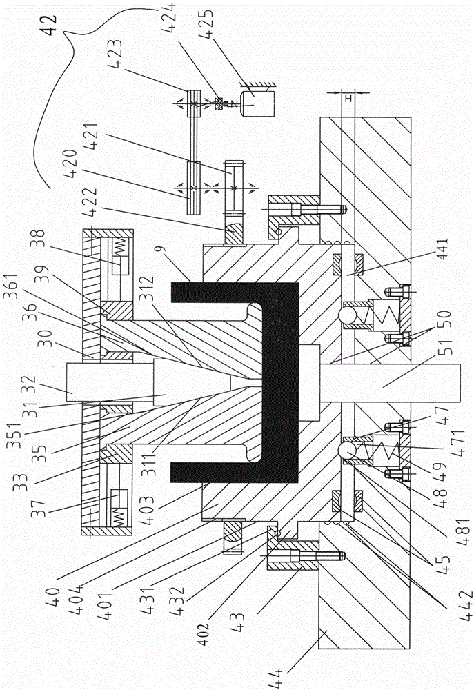
[0032] Such as Figure 5 As shown, an extrusion die for inner transverse ribs of cylindrical parts includes an upper die base 30, a double-acting press piercing cylinder joint 32, a wedge 31, a left punch 35, a right punch 36, and a left punch fixing plate 33 , the right punch fixed plate 39, the hydraulic cylinder 37 of the left push-pull fixed plate, the hydraulic cylinder 38 of the right push-pull fixed plate, the die 40, the limiter 43, the lower mold base 44, the thrust bearing plate 45, the steel ball bearing frame 47 , steel ball 48, spring 49, rotating device 42, left punch 35, right punch 36 are installed on the upper mold base 30 by left punch fixed plate 33, right punch fixed plate 39 respectively, left punch fixed plate 33, The right punch fixed plate 39 can slide left and right on the upper die base 30, one end of the hydraulic cylinder 37 of the left push-pull fixed plate is fixed on the upper die base 30, the other end is fixed on the left punch fixed plate 33, ...


PUM


Abstract

The invention discloses an inner transverse bar extrusion die for a cylindrical component. The inner transverse bar extrusion die comprises an upper die base, a wedge, a left convex die, a right convex die, a left convex die fixing plate, a right convex die fixing plate, a hydraulic cylinder of a left push-pull fixing plate, a hydraulic cylinder of a right push-pull fixing plate, a concave die, a stopper, a lower die base, a thrust bearing plate, a steel ball bearing bracket, a steel ball, a spring and a rotating device, wherein the left and the right convex dies are mounted on the upper die base and can slide left and right, the opposite side walls of the left and the right convex dies are slopes, and the wedge is embedded between the slope of the left convex die and the slope of the right convex die; the concave die is fixed on the lower die base through the stopper, and the upward and downward floatation of the concave die is realized on the lower die base through the spring. According to the inner transverse bar extrusion die provided by the invention, the separable convex dies and the floating type concave die are adopted, a workblank is vertically pressed down by the convex dies and driven to rotate by the concave die, a cylindrical wall is formed in a way that the workblank spirally flows upwards in the twisting process, cylinder fibers are spirally distributed and diagonally arranged, isotropy is realized, and the lateral and longitudinal comprehensive performance of the extruded component is improved.

Description

technical field [0001] The invention belongs to the metal extrusion forming industry, in particular to an extrusion forming method and an extrusion die for inner transverse ribs of cylindrical metal parts. Background technique [0002] For the extrusion of cylindrical parts, the traditional reverse extrusion method can only produce straight-walled cylinders. For the shape of the cylinder wall with inner ring ribs, it cannot be directly extruded, but the method of extrusion thickening the cylinder wall is used. The thick-walled cylinder is extruded, and the excess material is cut off by machining to become high ribs, which leads to a large waste of material and many processes. [0003] Such as figure 1 As shown, use punch 21, die 22 to extrude thickened cylindrical part 1, as figure 2 As shown, the excess wall thicknesses 12 and 13 of the upper and lower parts of the thickened cylinder wall 11 are subsequently cut off by machining, and the remaining middle wall thickness f...

Claims


Application Information

Patent Timeline
Patent Type & Authority Applications(China)
IPC IPC(8): B21C25/02
CPCB21C25/02
Inventor 张治民李国俊王强薛勇
Owner ZHONGBEI UNIV
Why Eureka
Try Eureka