
Down-cutting device for steel bar trusses

A cutting device and steel truss technology, applied in the field of steel truss machines, can solve the problems of inconvenient adjustment of the front and rear positions of the cutting mechanism, inability to flexibly adjust the cutting position, and low cutting efficiency, and achieve improved cutting efficiency, simple structure, and high cutting efficiency Effect

Inactive Publication Date: 2015-03-11
ZHEJIANG WILLING TECH
View PDF7 Cites 3 Cited by
  • Summary
  • Abstract
  • Description
  • Claims
  • Application Information

AI Technical Summary

Problems solved by technology

At present, part of the steel truss products are cut off manually with a cutting machine. The above method has the following disadvantages: Since the steel truss products are placed on the truss forming machine, cutting is troublesome and the cutting efficiency is low.
However, it is inconvenient to adjust the front and rear positions of the cutting mechanism, resulting in the inability to flexibly adjust the cutting position

Method used


Image

  • Down-cutting device for steel bar trusses
  • Down-cutting device for steel bar trusses
  • Down-cutting device for steel bar trusses

Examples


Embodiment Construction

[0015] The present invention will be further described in detail below in conjunction with the accompanying drawings and examples. The following examples are explanations of the present invention and the present invention is not limited to the following examples.

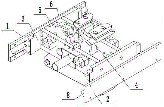
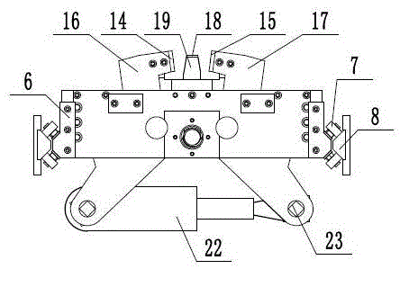
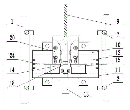
[0016] Such as figure 1 , figure 2 , image 3 with Figure 4 As shown, a lower cutting device for a steel bar truss includes a left frame 1, a right frame 2, a translation mechanism 3, and a lower cutting mechanism 4. The translation mechanism 3 realizes the front and rear translation of the lower cutting mechanism 4, and the cutting position can be flexibly adjusted. The cutting efficiency is improved, the lower cutting mechanism 4 can quickly realize the fast cutting of the lower end of the steel truss, the structure is simple, the cutting efficiency is high, and the cutting section is smooth. The left frame 1 and the right frame 2 are arranged symmetrically, and the translation mechanism 3 is arranged between...


PUM


Abstract

The invention provides a down-cutting device for steel bar trusses and belongs to the technical field of steel bar truss machines. The down-cutting device comprises a translation mechanism and a down-cutting mechanism; the translation mechanism comprises a supporting seat, translation rollers and a translation guide rail; translation supports are arranged at the left and right two ends of the supporting seat; the translation rollers are arranged on the outer sides of the translation supports, and the included angle of two translation rollers in each group is 90 degrees; the translation rollers can be arranged on the translation guide rail in such a manner of rolling back and forth; a lead screw is in threaded connection to a rear supporting plate; the down-cutting device comprises a left cutting tool, a right cutting tool, a fixed tool and a fixed tool holder; the middle sections of the left cutting tool and the right cutting tool are hinged to a front supporting plate; one end of a cutting cylinder is connected to the cylinder mounting base of a left tool holder, while the other end of the cutting cylinder is connected to the cylinder mounting base of a right tool holder; the cutting edge of the left cutting tool is opposite to the cutting edge of the right cutting tool; the fixed tool is mounted on the fixed tool holder; guide blocks are arranged on the two sides of the fixed tool holder. The down-cutting device can be flexibly adjusted in cutting position and improved in cutting efficiency, and is high in applicability.

Description

technical field [0001] The invention relates to the technical field of steel bar truss machines, in particular to a lower cutting device for steel bar trusses. Background technique [0002] The steel truss floor deck is a kind of unsupported pressure-type composite floor deck. The steel bar truss is finalized and processed in the background processing field. On-site construction needs to first fix the profiled plate on the steel beam with studs, and then place the steel bar truss Binding is carried out, and concrete is poured after acceptance. At present, in the construction of buildings, railways, bridges and other industries, in order to improve the bonding strength of concrete, steel bars are usually welded into steel bar trusses of different cross-sectional shapes and embedded in concrete. The section of the steel truss is generally triangular. The triangular truss includes an upper hanging bar and two lower hanging bars. The upper hanging bar and the two lower hanging...

Claims


Application Information

Patent Timeline
Patent Type & Authority Applications(China)
IPC IPC(8): B21F11/00
CPCB21F11/00
Inventor 蒋文星
Owner ZHEJIANG WILLING TECH
Learn More