Blisk electrolysis slotting machining annular electrode and technology method

A technology of integral blisks and ring electrodes, applied in electrochemical processing equipment, metal processing equipment, manufacturing tools, etc., can solve problems such as high cost, unstable quality, and low efficiency, and achieve low cost, long processing cycle, and Guarantee the effect of processing quality

Active Publication Date: 2015-03-11
SHENYANG LIMING AERO-ENGINE GROUP CORPORATION
View PDF5 Cites 10 Cited by
  • Summary
  • Abstract
  • Description
  • Claims
  • Application Information

AI Technical Summary

Problems solved by technology

Solve the high-efficiency machining of wide-chord and large-twisted blade-shaped channel slotting of large-scale fan overall blades, and solve the problems of low efficiency, high cost, and unstable quality of traditional machining methods

Method used


Image

  • Blisk electrolysis slotting machining annular electrode and technology method
  • Blisk electrolysis slotting machining annular electrode and technology method
  • Blisk electrolysis slotting machining annular electrode and technology method

Examples


Embodiment 1

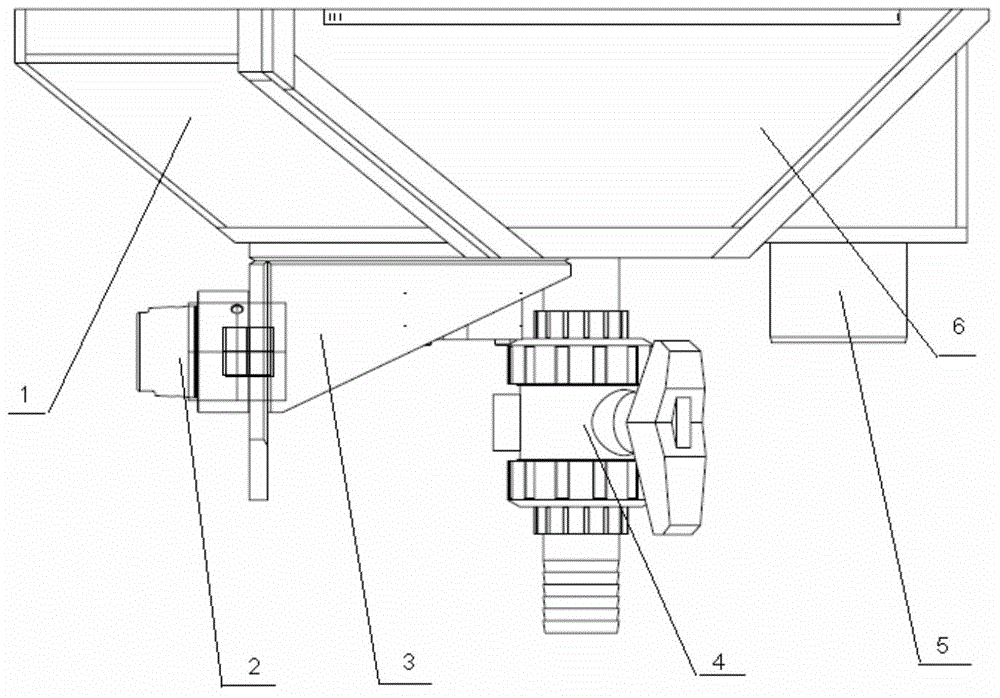
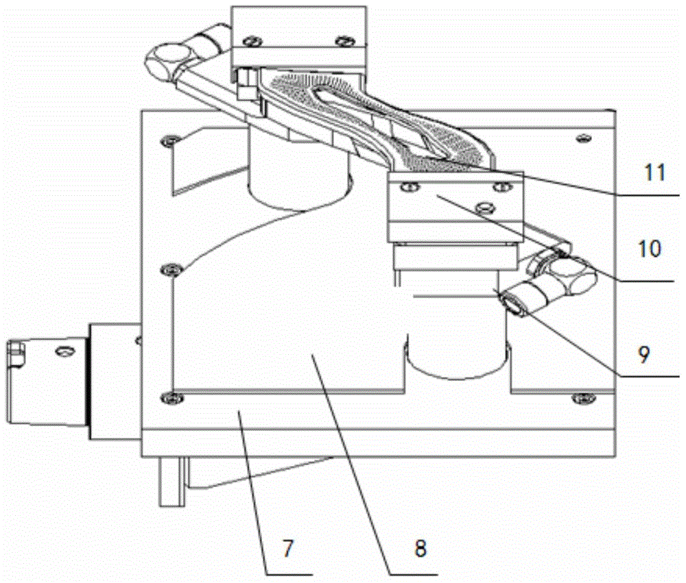
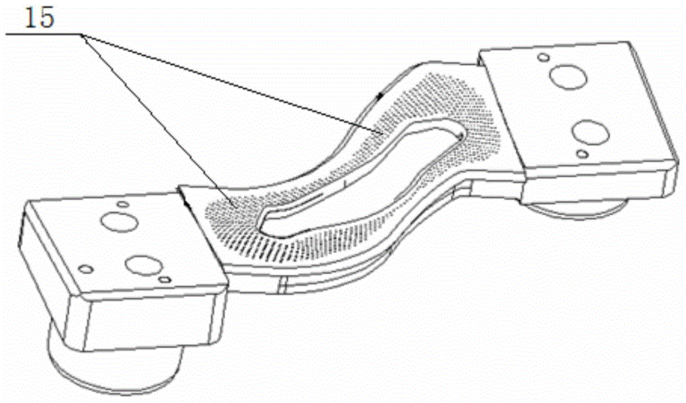
[0023] The grooved annular electrode is composed as follows: electrolyte tank 1, HSK hydraulic chuck 2, adapter plate 3, electrolyte discharge valve 4, electrolyte overflow port 5, electrolyte tank front baffle 6, working cathode Components and base 7; the working cathode components are composed as follows: a sacrificial anode protection plate 8, an electrolyte inlet pipe joint 9, an insulating briquetting block 10, and a working cathode 11; the electrolyte inlet pipe joint 9 is specifically two, The electrolyte inlet pipe joint 9 is respectively connected to the working cathode 11 through the insulating pressing block 10, and the integral blisk workpiece 14 is connected to the working cathode 11. The sacrificial anode protection plate 8 is located at the lower end of the working cathode, and the working cathode assembly is located at On the base 7, the working cathode assembly and the base 7 are located in the electrolyte tank 1. The HSK hydraulic chuck 2 is quickly positioned...

Embodiment 2

[0036] The grooved annular electrode is composed as follows: electrolyte tank 1, HSK hydraulic chuck 2, adapter plate 3, electrolyte discharge valve 4, electrolyte overflow port 5, electrolyte tank front baffle 6, working cathode Components and base 7; the working cathode components are composed as follows: a sacrificial anode protection plate 8, an electrolyte inlet pipe joint 9, an insulating briquetting block 10, and a working cathode 11; the electrolyte inlet pipe joint 9 is specifically two, The electrolyte inlet pipe joint 9 is respectively connected to the working cathode 11 through the insulating pressing block 10, and the integral blisk workpiece 14 is connected to the working cathode 11. The sacrificial anode protection plate 8 is located at the lower end of the working cathode, and the working cathode assembly is located at On the base 7, the working cathode assembly and the base 7 are located in the electrolyte tank 1. The HSK hydraulic chuck 2 is quickly positioned...

Embodiment 3

[0044] The grooved annular electrode is composed as follows: electrolyte tank 1, HSK hydraulic chuck 2, adapter plate 3, electrolyte discharge valve 4, electrolyte overflow port 5, electrolyte tank front baffle 6, working cathode Components and base 7; the working cathode components are composed as follows: a sacrificial anode protection plate 8, an electrolyte inlet pipe joint 9, an insulating briquetting block 10, and a working cathode 11; the electrolyte inlet pipe joint 9 is specifically two, The electrolyte inlet pipe joint 9 is respectively connected to the working cathode 11 through the insulating pressing block 10, and the integral blisk workpiece 14 is connected to the working cathode 11. The sacrificial anode protection plate 8 is located at the lower end of the working cathode, and the working cathode assembly is located at On the base 7, the working cathode assembly and the base 7 are located in the electrolyte tank 1. The HSK hydraulic chuck 2 is quickly positioned...


PUM


Abstract

The invention discloses a blisk electrolysis slotting machining annular electrode and a technology method. The slotting machining annular electrode is composed of an electrolyte slot (1), an HSK hydraulic chuck (2), a through connection disc (3), an electrolyte draining valve (4), an electrolyte overflow opening (5), an electrolyte slot front baffle (6), a working cathode component and a base (7). The working cathode component is composed of a sacrificial anode protection plate (8), two electrolyte inlet pipe joints (9), insulation pressing blocks (10) and working cathodes (11). The electrolyte inlet pipe joints (9) are connected with the working cathodes (11) respectively through the insulation pressing blocks (10). The blisk electrolysis slotting machining annular electrode and the technology method solve the problems that a traditional machining method is low in efficiency, high in cost and unstable in quality.

Description

technical field [0001] The invention relates to the technical field of structural design and application of ring electrodes for electrolytic grooving of integral blisks, and in particular provides a ring electrode for electrolytic grooving of integral blisks and a process method. Background technique [0002] The principle of electrolytic machining is a non-traditional cutting method that uses the principle that metals can undergo anodic dissolution in the electrolyte to remove materials and shape workpieces. In electrolytic machining, the tool (knife) is connected to a DC power supply as the cathode and the workpiece as the anode. In the electrolyte, the cathode of the tool moves to the anode of the workpiece at a certain speed, and the charge exchange occurs between the tool and the workpiece. The material of the anode workpiece is dissolved and taken away by the high-speed flowing electrolyte, thereby achieving very precise processing requirements. [0003] It is urgentl...

Claims


Application Information

Patent Timeline
IPC IPC(8): B23H7/12B23H3/00
CPCB23H3/00B23H7/12
Inventor 朱海南杨涧石于冰李伟
Owner SHENYANG LIMING AERO-ENGINE GROUP CORPORATION
Why Eureka
Try Eureka