Eureka AIR delivers breakthrough ideas for toughest innovation challenges, trusted by R&D personnel around the world.

Mold for dry casing production

A dry-type sleeve and mold technology, applied in the field of optical fiber and cable manufacturing equipment, can solve problems such as affecting the transmission performance and temperature performance of the optical cable, unstable sleeve size, affecting the performance of the optical cable, etc. Round, simple structure

Active Publication Date: 2017-03-08
SHANTOU HIGH TECH ZONE AOXING OPTICAL COMM EQUIP
View PDF7 Cites 0 Cited by
  • Summary
  • Abstract
  • Description
  • Claims
  • Application Information

AI Technical Summary

Problems solved by technology

However, due to the lack of grease lubrication and isolation in the casing, the optical fiber is easy to contact the casing wall in a high temperature state, resulting in excessive and unstable excess length, which directly affects the transmission performance and temperature performance of the optical cable; another On the one hand, due to the lack of filling of the inner space of the sleeve with ointment, the sleeve is prone to flattening and the size of the sleeve is unstable, which further affects the performance of the optical cable

Method used


Image

  • Mold for dry casing production
  • Mold for dry casing production
  • Mold for dry casing production

Examples


Embodiment Construction

[0017] The idea, specific structure and technical effects of the present invention will be further described below in conjunction with the accompanying drawings, so as to fully understand the purpose, features and effects of the present invention.

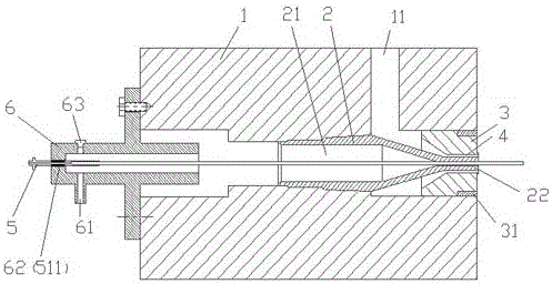
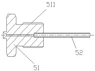
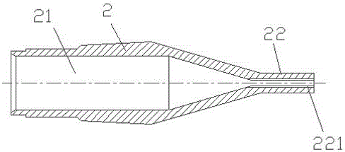
[0018] refer to figure 1 , 2 , 3, and 4, the present invention relates to a mold for dry casing production, including a mold core 2 and a mold cover 3 assembled on the extruder head 1, the mold core 2 has a through hole 21 and extrusion Nozzle 22, the outer periphery of the extrusion nozzle 22 forms an extrusion gap 4 with the extrusion port of the die cover 3, and the extrusion gap 4 communicates with the material inlet 11 of the extruder head 1. The die cover 3 is connected to the extruder head 1 through a fastener 31 , and the fastener 31 can be connected to the extruder head 1 through threads or screws. The mold also includes a hollow threading needle 5, one end of the threading needle 5 passes through the through hole 21 of ...


PUM


Abstract

The invention relates to the technical field of optical fiber and optical cable manufacturing equipment, in particular to a dry-type mold for sleeve production. The mold comprises a mold core, mold cover and a hollow silk threading needle which are assembled on an extruder head, wherein the mold core is provided with a middle through hole and an extruding nozzle, and an extruding gap is formed between the periphery of the extruding nozzle and an extruding opening of the mold cover; one end of the silk threading needle penetrates through the middle through hole of the mold core and extends out of the mold cover, the other end of the silk threading needle is connected with a fixing element through threads, and the fixing element is assembled on the extruder head and is provided with a gas inlet hole. Stabilized gas introduced from the gas inlet hole of the fixing element is continuously and steadily blown out of the extruding nozzle of the mold core, so that after the plastic is extruded and is at a high temperature melting state, the extruded plastic remains a steady outer diameter and a rounded shape, besides, gas with a lower temperature can also accelerate the cooling of the inner wall of the sleeve and effectively avoid the phenomena that the excess length of fibers in the sleeve is too long, the excess length is not steady, the sleeve becomes flat, and the size of the sleeve is not steady, and the transmission property, the mechanical and physical properties and the temperature property of the optical cable are ensured.

Description

technical field [0001] The invention relates to the technical field of optical fiber and cable manufacturing equipment, in particular to a mold for dry sleeve production. Background technique [0002] In the current production of optical cables, the production process of optical fiber sleeves is filled with fiber paste. Since the fiber paste is a paste-like substance, it will cause troubles in cleaning the production and use of optical cables. Nowadays, with the rise of fiber optic access to the home, optical cable access networks generally require clean, environmentally friendly, convenient splicing, and light-weight optical cables. Dry optical cables are an ideal choice. However, due to the lack of grease lubrication and isolation in the casing, the optical fiber is easy to contact the casing wall in a high temperature state, resulting in excessive and unstable excess length, which directly affects the transmission performance and temperature performance of the optical cab...

Claims


Application Information

Patent Timeline
Patent Type & Authority Patents(China)
IPC IPC(8): B29C47/20B29C47/86B29C48/32
CPCB29C48/30B29C48/32B29C48/9115
Inventor 凌振山戴德彦李钊庄经荣
Owner SHANTOU HIGH TECH ZONE AOXING OPTICAL COMM EQUIP
Why Eureka
Eureka Blog
Learn More