Porous inflow hedging energy dissipation structure of hydraulic structure

A technology for hydraulic structures and energy dissipation, applied in construction, water conservancy engineering, marine engineering and other directions, can solve the problems of low energy dissipation rate of stilling pool, cavitation damage, low energy dissipation rate of stilling pool, etc. Input cost, the effect of reducing the height and width of the tail sill

Active Publication Date: 2015-03-11
SICHUAN UNIV
View PDF3 Cites 18 Cited by
  • Summary
  • Abstract
  • Description
  • Claims
  • Application Information

AI Technical Summary

Problems solved by technology

[0005] However, engineering practice has proved that when the flow rate is high, the side walls of auxiliary facilities are prone to local negative pressure, resulting in cavitation damage; , auxiliary energy dissipation facilities are often damaged by violent impact
[0006] In addition, both model tests and engineering practice have proved that the energy dissipation rate of conventional stilling basins is relatively low, generally around 60% to 70%, sometimes even lower
In view of the insufficient layout of conventional hydraulic structures in the prior art, it is necessary to change the design idea. By changing the layout of hydraulic structures, it is possible to make full use of the advantages of the existing stilling pool and overcome the existing problems as much as possible. Disadvantages of low energy dissipation rate of stilling basin

Method used


Image

  • Porous inflow hedging energy dissipation structure of hydraulic structure
  • Porous inflow hedging energy dissipation structure of hydraulic structure
  • Porous inflow hedging energy dissipation structure of hydraulic structure

Examples


Embodiment 1

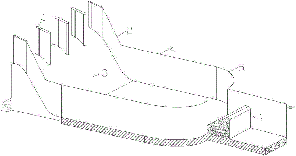
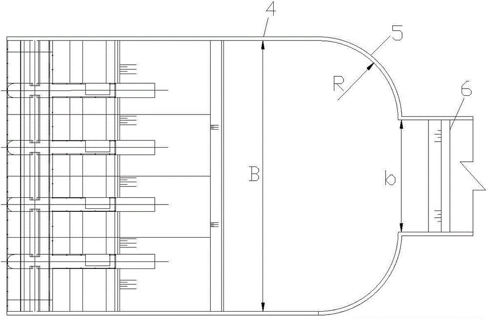
[0025] The porous inflow counter energy dissipation structure of the hydraulic structure of this embodiment has a structure as attached figure 1 And attached figure 2 As shown, it includes an overflow dam where the water body flows from its top, a stilling basin located behind the overflow dam, and a tail sill 6 located at the outlet of the stilling basin. The crest of the overflow dam is an arc surface, and the overflow The surface 3 is a plane, and the crest of the dam is designed with a number of gate piers 1 that divide the water body flow area into several openings, so that the water body can leak into the stilling pool from the multi-holes. The dam is 50 meters high and 80 meters wide; The pool has an inlet width of 75 meters, the bottom of the pool is connected to the overflow surface 3 of the overflow dam, and the protective side wall 4 of the stilling pool is connected to the side wall 2 of the overflow surface of the overflow dam. 50m downstream of the water jump ...

Embodiment 2

[0027] The porous inflow counter energy dissipation structure of the hydraulic structure of this embodiment has a structure as attached figure 1 And attached figure 2 As shown, it includes an overflow dam where the water body flows from its top, a stilling basin located behind the overflow dam, and a tail sill 6 located at the outlet of the stilling basin. The crest of the overflow dam is an arc surface, and the overflow The surface 3 is a plane, and the crest of the dam is designed with a number of gate piers 1 that divide the water body flow area into several orifices, so that the water body can be discharged into the stilling pool from the porous, the dam is 80 meters high, and the dam is 60 meters wide; the stilling pool , its inlet width dam is 55 meters wide, the bottom of the pool is connected with the overflow surface 3 of the overflow dam, the protective side wall 4 of the stilling pool is connected with the side wall 2 of the overflow surface of the overflow dam, a...


PUM


Abstract

The invention discloses a porous inflow hedging energy dissipation structure of a hydraulic structure. The hydraulic structure comprises an overflow dam and an absorption basin, wherein a water body flows through the top of the overflow dam; the absorption basin is arranged behind the overflow dam; the bottom of the absorption basin is connected with the overflow surface of the overflow dam; protective edge walls of the absorption basin are connected with edge walls of the overflow surface of the overflow dam; the top of the overflow dam is provided with multiple gate piers for dividing a water body flowing area into multiple holes, so that the water body is discharged into the absorption basin from the multiple holes; and the protective edge walls are symmetrically provided with steering edge wall sections at the downstream of the head part of a hydraulic jump by 50-80 m for narrowing an outlet of the absorption basin, so that the water current discharged from the holes of the overflow dam flows through the narrowed outlet of the absorption basin to realize the rising of the water surface in the absorption basin so as to achieve quick transition of the flowing state of the water current from rapid current to slow current. The structure has such advantages as prominent energy dissipation effect and low construction cost of the hydraulic structure.

Description

technical field [0001] The invention belongs to the field of flood discharge and energy dissipation in water conservancy and hydropower projects, and in particular relates to a water flow energy dissipation structure including an overflow dam and a hydraulic structure arranged therein. Background technique [0002] In the construction of water conservancy and hydropower projects, gravity dams and gate dams are commonly used types of overflow dams. Due to the need for flood discharge and energy dissipation, a stilling pool of a certain scale is often built behind the overflow dam. The strong tumbling caused by the hydraulic jump and a large amount of air entrainment are used to dissipate energy. With the improvement of modern dam-building technology, the overall scale of dam construction is developing towards the trend of high water head and large flow, and the size of the downstream stilling basin has also increased sharply. [0003] As the height of the dam or the water le...

Claims


Application Information

Patent Timeline
Patent Type & Authority Applications(China)
IPC IPC(8): E02B8/06
CPCE02B8/06
Inventor 邓军刘文许唯临田忠张法星刘善均张建民王韦曲景学周茂林
Owner SICHUAN UNIV
Why Eureka
Try Eureka