
A structure and method for increasing the height of corridor ceiling

A technology of suspended ceiling and height, applied in the direction of ceiling, building components, building structure, etc., can solve the problems of small ceiling elevation, achieve the effect of raising the ceiling elevation, saving vertical space, and saving construction materials

Active Publication Date: 2016-10-12
SHANGHAI INSTALLATION ENG GRP
View PDF5 Cites 0 Cited by
  • Summary
  • Abstract
  • Description
  • Claims
  • Application Information

AI Technical Summary

Problems solved by technology

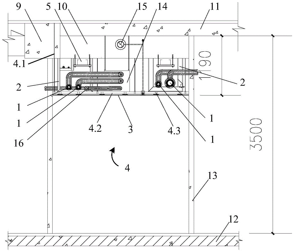
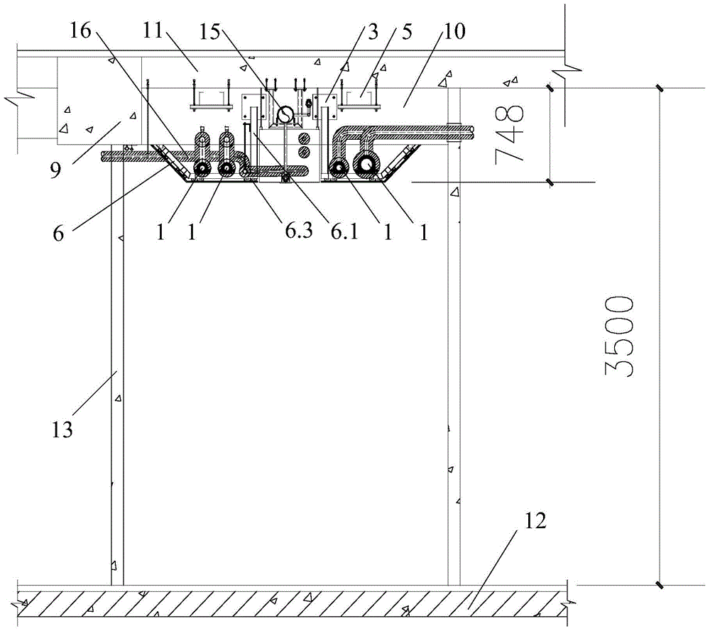
[0005] In order to solve the problem that the corridor space is narrow and the ceiling elevation is too low in the prior art, the present invention provides a structure and method for increasing the height of the corridor ceiling, which makes full use of the space between the beam and the floor roof to set up a strong wire trough, thereby significantly improving the air conditioner. The elevation of the cold water supply and return pipes and the ceiling, and by combining the existing pipeline support and hanger with the decorative ceiling support and hanger into a combined pipeline and ceiling support and hanger, the space occupied by the support and hanger can be compressed, and the corridor ceiling can be further raised elevation

Method used


Image

  • A structure and method for increasing the height of corridor ceiling
  • A structure and method for increasing the height of corridor ceiling
  • A structure and method for increasing the height of corridor ceiling

Examples


Embodiment Construction

[0026] A structure and method for increasing the height of the corridor ceiling proposed by the present invention will be further described in detail below in conjunction with the accompanying drawings and specific embodiments. Advantages and features of the present invention will be apparent from the following description and claims. The technical content and features of the present invention will be described in detail below by referring to the illustrated embodiments in conjunction with the accompanying drawings. It should be further noted that all the drawings are in very simplified form and use imprecise scales, and are only used to facilitate and clearly assist the purpose of illustrating the embodiments of the present invention.

[0027] see Figure 3 to Figure 5 , this embodiment discloses a structure for increasing the height of the corridor ceiling, including the pipeline ceiling combination support and hanger 6 arranged along the longitudinal direction of the main ...


PUM


Abstract

The invention provides a structure and a method for increasing the height of a corridor ceiling. The structure comprises a pipeline ceiling combined supporting hanger, a strong current wire groove and an air-conditioner cold water supply and water returning pipe which are arranged along the longitudinal direction of a main beam, wherein the pipeline ceiling combined supporting hanger is hung to a secondary beam or a floor top plate; the air-conditioner cold water supply-return pipe is directly arranged on the pipeline ceiling combined supporting hanger; the strong current wire groove is hung below the floor top plate. Due to the fact that except the part, which passes the secondary beam and is provided with a lower concave part used for crossing the secondary beam, of the strong current wire groove, the other parts of the strong current wire groove are arranged in the space between the bottom surface of the secondary beam and the bottom surface of the floor top plate, the ceiling elevation of a corridor is obviously improved. Due to the fact that a pipeline supporting hanger and a ceiling supporting hanger are combined into the pipeline ceiling combined supporting hanger, and the pipeline ceiling combined supporting hanger simultaneously plays the role of supporting the air-conditioner cold water supply-return pipe, a keel and a ceiling, so that a main keel in the original ceiling supporting hanger is eliminated, and the ceiling is further lifted.

Description

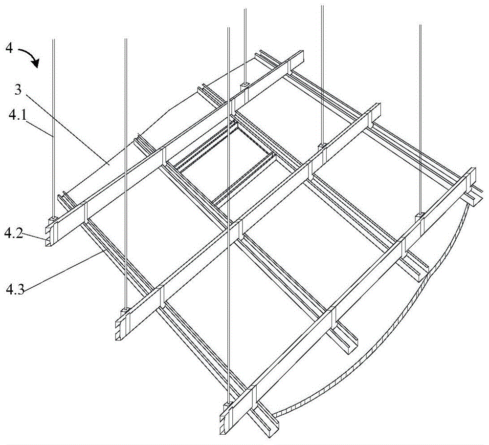
technical field [0001] The invention relates to the technical field of auxiliary equipment for building structures, in particular to a structure and method for increasing the height of a corridor ceiling. Background technique [0002] At present, the traditional mechanical and electrical pipelines and decorative ceilings in the corridor ceiling of civil buildings use their own support and hangers. After the mechanical and electrical construction is completed, decoration construction is required, and the construction may collide with each other, especially in the narrow space, so the ceiling elevation has to be lowered. [0003] see figure 1 , the air-conditioning cold water supply and return pipe 1 adopts an independent pipeline support hanger 2, and the decorative ceiling 3 also adopts an independent ceiling support hanger 4. figure 1 2 shows that there are two sets of air-conditioning cold water supply and return pipes 3 respectively supported by respective pipeline supp...

Claims


Application Information

Patent Timeline
Patent Type & Authority Patents(China)
IPC IPC(8): E04B9/00E04B9/18F16L3/02
Inventor 施志义袁鹏飞汪志桃
Owner SHANGHAI INSTALLATION ENG GRP
Learn More