A Three-Stage Jet Refrigeration System

A refrigeration system and injection technology, which is applied in refrigerators, refrigeration components, refrigeration and liquefaction, etc., can solve the problems of complex systems and limited improvement of ejector operating conditions, and achieve compact space layout, saving working fluid volume, and reducing The effect of superheat

Active Publication Date: 2016-10-12
SHANDONG UNIV
View PDF10 Cites 0 Cited by
  • Summary
  • Abstract
  • Description
  • Claims
  • Application Information

AI Technical Summary

Problems solved by technology

But the use of economizer or subcooler still complicates the system
And its two-stage injectors are all gas injectors, which have little influence on the injection ratio and have limited improvement on the operating conditions of the injectors

Method used


Image

  • A Three-Stage Jet Refrigeration System
  • A Three-Stage Jet Refrigeration System

Examples


Embodiment Construction

[0020] The present invention is described in detail below in conjunction with accompanying drawing:

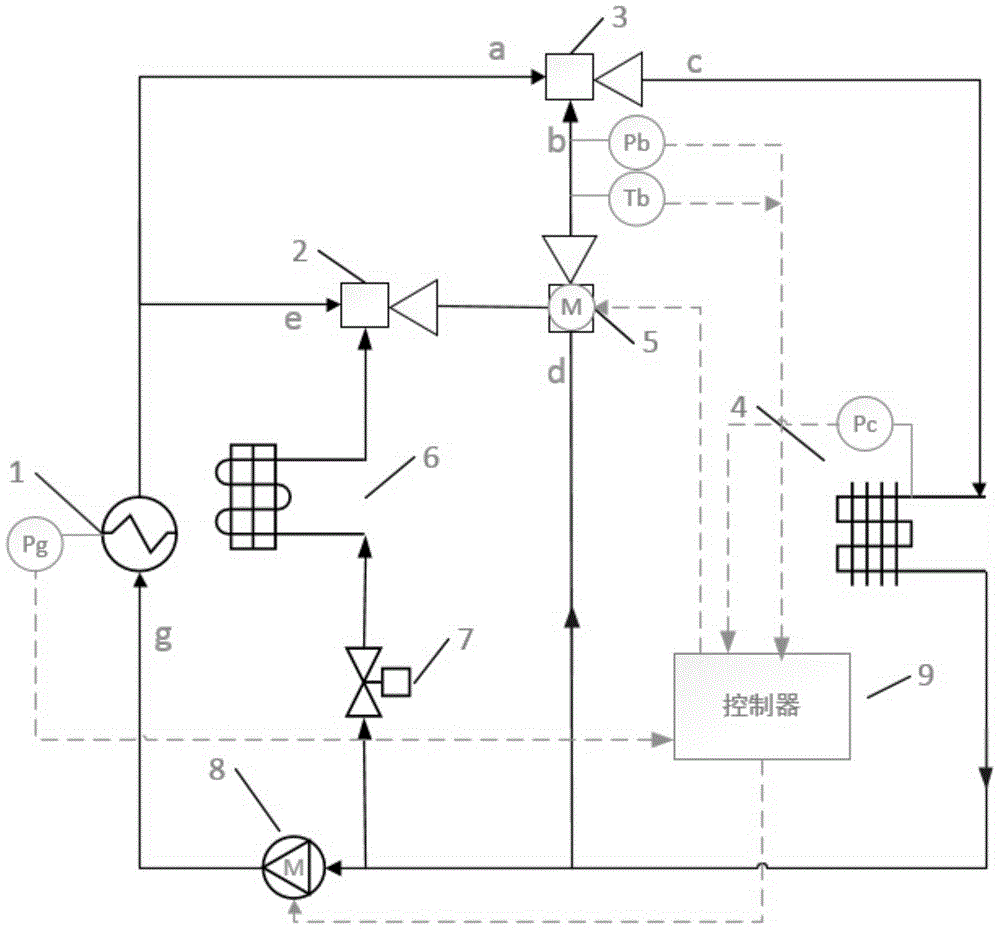
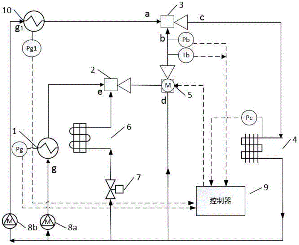
[0021] The present invention aims to solve the problems of low injection ratio, low energy efficiency, small pressure ratio, high temperature of the secondary flow inlet in the middle of the ejector, and large volume of the secondary ejector in the existing two-stage ejector refrigeration system, so as to improve the compression ratio , injection ratio and system energy efficiency.

[0022] like figure 1 As shown, a three-stage ejector refrigeration system includes a condenser 4, and the output end of the condenser 4 is divided into three circuits, one of which is connected to the second-stage ejector 5, the other is connected to the pump 8, and the third is sequentially connected to the throttling The valve 7, the evaporator 6 and the first-stage injector 2 are connected, and the output of the first generator 1 is divided into two routes, one of which is connected with the f...


PUM


Abstract

The invention discloses a three-stage injection type refrigeration system. The three-stage injection type refrigeration system comprises a condenser; the output end of the condenser is divided into three routes, one route is connected with the second stage injector, another route is connected with a pump, and the third route is sequentially connected with a throttle valve, an evaporator and the first stage injector; the output of a generator is divided into two routes, one route is connected with the first stage injector, the other route is connected with the third stage injector; and both the first stage injector and the third stage injector are connected with the second stage injector. The three-stage injection type refrigeration system has an energy-saving effect, effectively reduces the quantity of working gas required by the injectors, reduces the quantity of heat required by the generator, increases the entrainment ratio, reduces the volume of the injectors, increases the energy efficiency by about 5%, and achieves a greater pressure ratio. The three-stage injection type refrigeration system is simple in configuration, low in manufacturing cost, and compact in structure.

Description

technical field [0001] The invention relates to the technical field of refrigeration, in particular to a three-stage injection refrigeration system. Background technique [0002] Ejection refrigeration is a refrigeration technology driven by thermal energy, which can make full use of industrial waste heat, solar heat and other low-grade heat sources. It consumes little mechanical energy, has simple equipment, reliable operation and low cost. Its working medium can be carbon dioxide, water, hydrocarbons and other green and environment-friendly natural substances. [0003] However, its disadvantages are that the ejector has a small compression ratio and a high cooling temperature; and its operation is affected by the back pressure, and the injection ratio is small. [0004] Patent Application No. 201210116545.X proposes "a self-cascading ejector refrigerator", which uses a mixed working fluid and two ejectors to achieve a larger pressure ratio, but the structure is complex, ...

Claims


Application Information

Patent Timeline
Patent Type & Authority Patents(China)
IPC IPC(8): F25B19/04F25B49/00
CPCF25B19/04F25B49/00F25B2600/00
Inventor 赵红霞王雷匙明申
Owner SHANDONG UNIV
Why Eureka
Try Eureka