a test fixture

A test fixture and test circuit technology, applied in the direction of the measurement device shell, etc., can solve the problems of damage to the DUT and narrow test bandwidth, and achieve the effects of expanding the radio frequency bandwidth, improving the test bandwidth, and preventing impedance mismatch.

Active Publication Date: 2017-06-30
JIANGSU CAS IGBT TECHNOLOGY CO LTD
View PDF7 Cites 0 Cited by
  • Summary
  • Abstract
  • Description
  • Claims
  • Application Information

AI Technical Summary

Problems solved by technology

[0004] The invention provides a test fixture to solve the technical problems in the prior art that the test fixture is either easy to cause damage to the device under test, or the test bandwidth is narrow

Method used


Image

  • a test fixture
  • a test fixture
  • a test fixture

Examples


Embodiment Construction

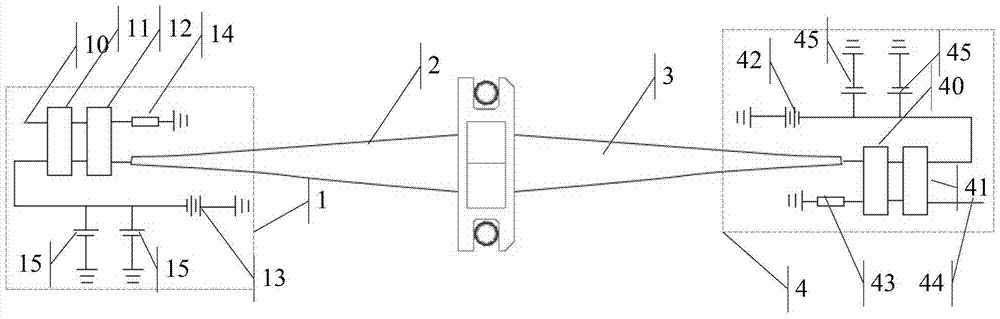
[0029] The invention provides a test fixture to solve the technical problems in the prior art that the test fixture either easily causes damage to the tested part or the test bandwidth is narrow.

[0030] The technical solution in the embodiment of the present application is to solve the above-mentioned technical problems, and the general idea is as follows:

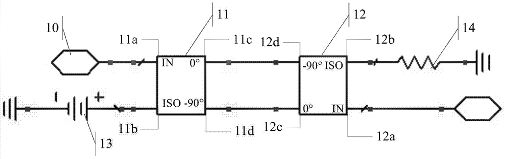
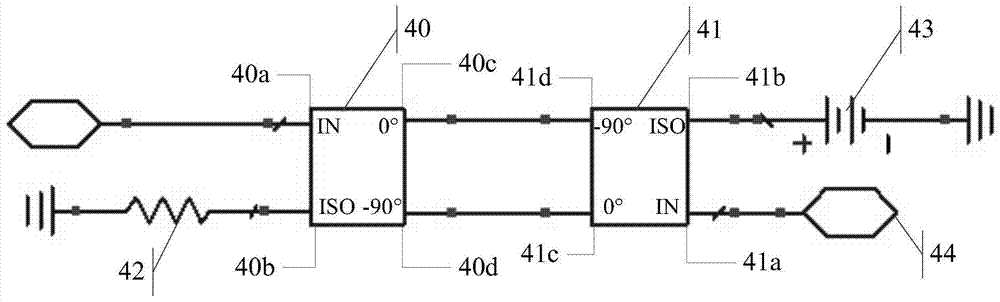
[0031] A test fixture is provided, comprising: a first test circuit, a first Stan transform gradient microstrip line, a second Stein transform gradient microstrip line and a second test circuit, wherein the first test circuit includes a first 90° hybrid bridge and a second 90° hybrid bridge, the second test circuit contains a third 90° hybrid bridge and a fourth 90° hybrid bridge, where the four 90° hybrid bridges can both act as polarization circuits, thereby preventing impedance At the same time, the combination of four 90° hybrid bridges and two Stein transform gradient microstrip lines can also expand the RF bandwidt...


PUM


Abstract

The invention relates to the field of radio frequency and microwave measurement, and discloses a test fixture to solve the technical problems in the prior art that the test fixture either easily causes damage to the device under test or has a narrow test bandwidth. The test fixture includes: a first test circuit , the first Stan transformation gradient microstrip line, the second Stan transformation gradient microstrip line and the second test circuit, wherein the first test circuit comprises a first 90° hybrid bridge and a second 90° hybrid bridge, and the second test circuit Contains the third 90° hybrid bridge and the fourth 90° hybrid bridge, the four 90° hybrid bridges can not only play the role of RF open circuit, so as to prevent impedance mismatch, but at the same time, the four 90° hybrid bridges and the two The Stein transform gradient microstrip line can also expand the radio frequency bandwidth, thereby achieving the technical effect of improving the radio frequency test bandwidth while ensuring the safety of the device under test.

Description

technical field [0001] The invention relates to the field of radio frequency microwave measurement, in particular to a test fixture. Background technique [0002] The test fixture belongs to a category under the fixture, which is a kind of fixture specially used for testing and testing the function, power calibration, life, and performance of the product. In the prior art, microwave power tubes can be tested through a 50Ω test fixture. However, the test fixture is not designed with an impedance transformation function, and its PA (Power Amplifier: Power Amplifier) ​​has a serious impedance mismatch problem, resulting in low-frequency oscillations. In this case, the DUT is easily burned. [0003] In order to solve the above problems, a test fixture for supplying power through a bias circuit has been produced in the prior art, which can be used in a Load pull (load pulling) system to test a packaged power amplifier tube. This kind of fixture bias circuit uses 1 / 4 wavelength ...

Claims


Application Information

Patent Timeline
Patent Type & Authority Patents(China)
IPC IPC(8): G01R1/04
Inventor 丛密芳任建伟李科杜寰
Owner JIANGSU CAS IGBT TECHNOLOGY CO LTD
Why Eureka
Try Eureka