
A two-way operating mechanism

A two-way operation, action mechanism technology, applied in contact drive mechanism, electrical components, electrical switches and other directions, can solve the problems of complex processing and assembly, no interlocking, misoperation, etc., to achieve simple processing, reduce failure rate, and avoid mistakes. effect of operation

Active Publication Date: 2016-05-18
WUXI VITZRO ELECTROMECHANICAL
View PDF5 Cites 0 Cited by
  • Summary
  • Abstract
  • Description
  • Claims
  • Application Information

AI Technical Summary

Problems solved by technology

[0003] The technical problem to be solved by the present invention is: the grounding mechanism on the existing two-way switching ring network equipment is two independent mechanisms, which are not integrated, the processing and assembly are complicated, and there is no interlock between the two, so errors occur. The problem of the relative increase in the probability of operation

Method used


Image

  • A two-way operating mechanism
  • A two-way operating mechanism
  • A two-way operating mechanism

Examples


Embodiment 1

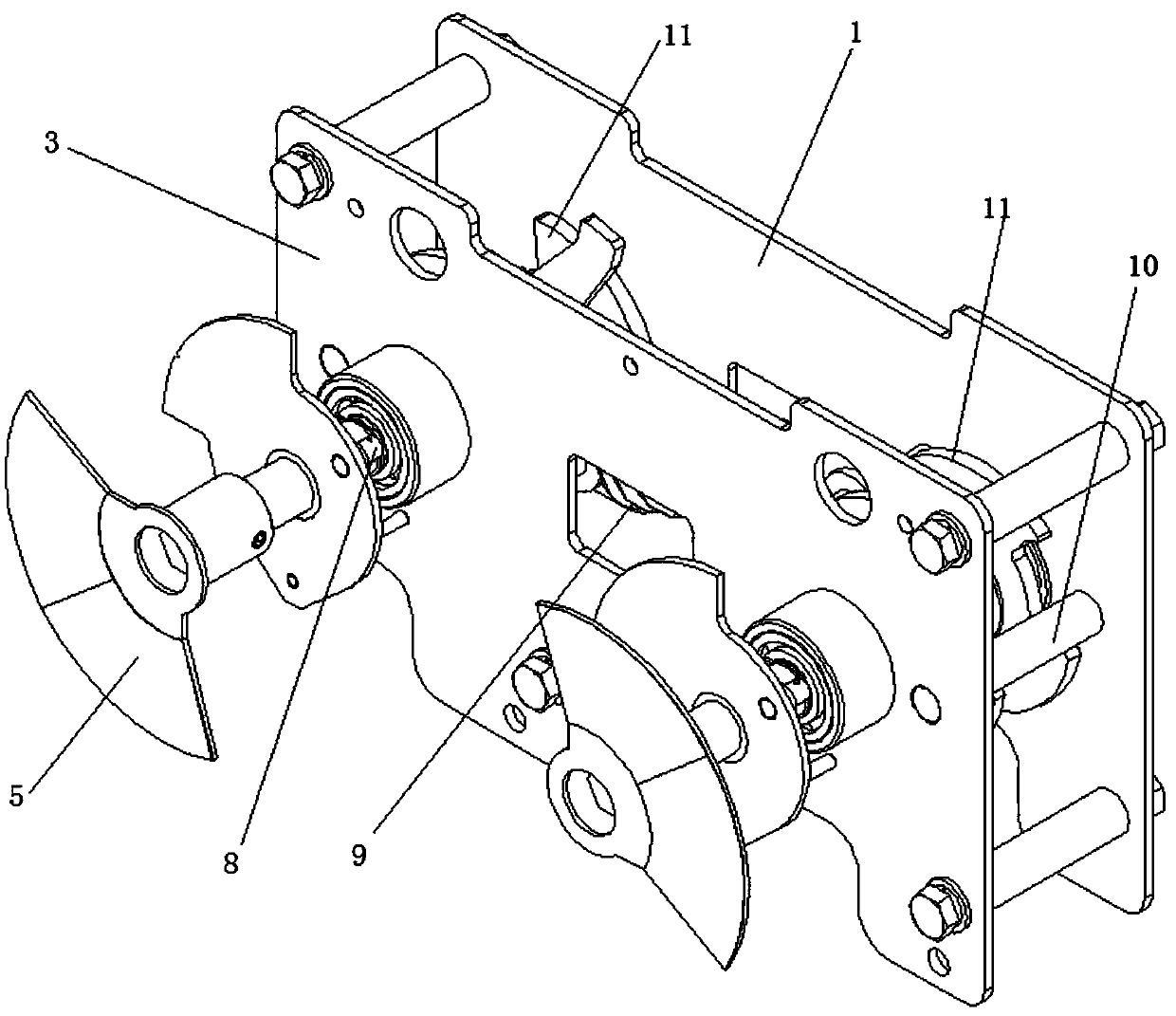
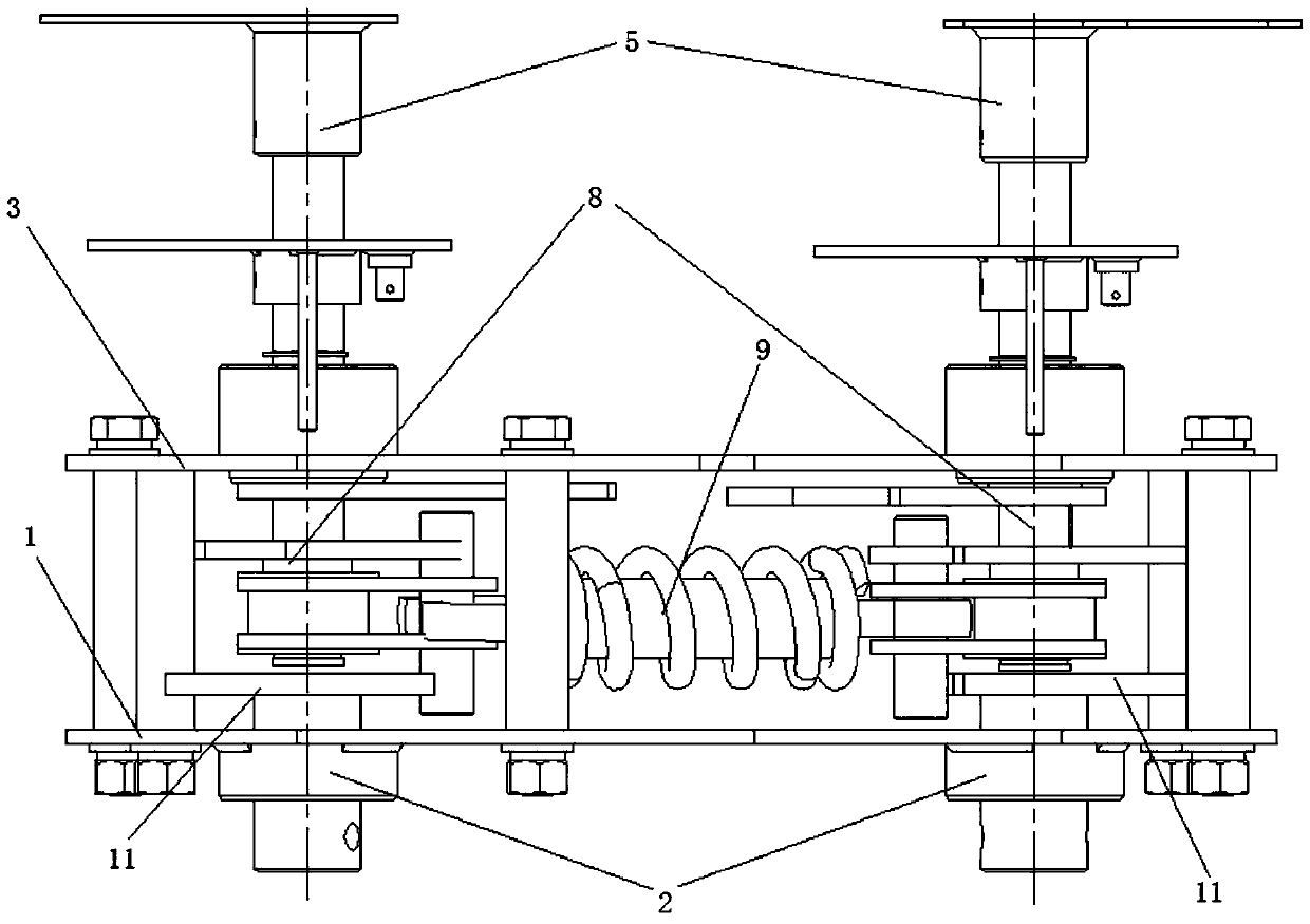
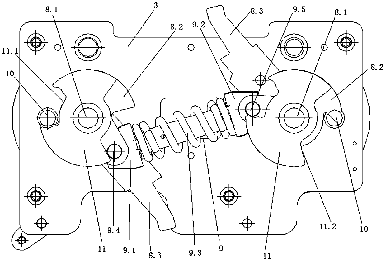
[0044] The two-way operating mechanism in this embodiment includes a front mounting plate 3, a rear mounting plate 1, two mechanical action mechanisms 8, two spacer posts 10, a spring action mechanism 9, two driven spacer plates 11 and a driven shaft joint 2; as Figure 1-Figure 9 shown.

[0045]The mechanical action mechanism 8 includes a rotating shaft 8.1, a manual operation plate 5, a limit plate 8.2 and a baffle plate 8.3; as Figure 7 and Figure 8 shown.

[0046] The spring action mechanism 9 includes a first shift fork 9.1, a second shift fork 9.2, a compression spring 9.3, a first rotating shaft limit post 9.4, a second rotating shaft limit post 9.5, a first rotating connecting plate 9.6 and a second rotating connecting plate 9.7 ;like Figure 9 shown.

[0047] The rear mounting plate 1 in this embodiment is arranged in parallel with the front mounting plate 3 through bolt connection; two mechanical action mechanisms 8 are all arranged on the front mounting plate...

Embodiment 2

[0060] Compared with Embodiment 1, a set of mechanical self-locking mechanism 6 is added to the bidirectional operating mechanism in this embodiment, and the rest of the mechanisms are the same as those in Embodiment 1. Such as Figure 10 and 11 shown.

[0061] The mechanical self-locking mechanism 6 in this embodiment includes an indicator plate 6.1, a first linkage plate 6.2, a connecting plate 6.3, a second linkage plate 6.4 and a lead-out shaft 6.5; the indicator plate 6.1 is fixedly arranged on the rotating shaft 8.1; the first linkage plate One end of 6.2 is fixedly connected to indicator plate 6.1, and the other end is fixedly connected to one end of connecting plate 6.3; the other end of connecting plate 6.3 is fixedly connected to one end of second linkage plate 6.4; the other end of second linkage plate 6.4 is fixedly connected to lead-out shaft 6.5; The middle positions of the two linkage plates 6.4 are set on the front mounting plate 3 through the rotation of the...


PUM


Abstract

The invention discloses a bidirectional operation mechanism and solves the problem that the probability of error operation is relatively high as grounding mechanisms on existing bidirectional switching looped network equipment are two independent mechanisms, not integrated, complicated in processing and assembling and not interlocked. According to the technical scheme of the bidirectional operation mechanism, the bidirectional operation mechanism comprises a front mounting plate, a rear mounting plate, two mechanical action mechanisms, two limiting columns, a spring action mechanism, two driven limiting plates and a driven shaft connector. The bidirectional operation mechanism has the advantages that the operation mechanism adopts an integrated grounding mechanism and is simple to process, easy and convenient to mount, the interlocking function between mechanisms is realized, and the situation of error operation cannot be caused, so that compared with an existing grounding mechanism, the operation mechanism is safe, reliable, low in cost and simple and convenient to mount; compared with a conventional operation mechanism, the operation mechanism is simple and convenient to operate, small in volume, light in weight, simple in structure and low in fault rate; the structure of the integrated grounding mechanism is favorable for effective work of equipment, the integrated grounding mechanism is low in cost and easy to learn and operate by a user, and the error operation of two-side simultaneous switching-on cannot be caused.

Description

technical field [0001] The invention relates to a bidirectional operating mechanism, in particular to a grounding operating mechanism used for bidirectional automatic switching ring network equipment. Background technique [0002] The grounding mechanism on the existing two-way switching ring network equipment is two independent mechanisms, which are not integrated, the processing and assembly are complicated, and there is no interlock between the two, so the probability of misoperation is relatively high. Contents of the invention [0003] The technical problem to be solved by the present invention is: the grounding mechanism on the existing two-way switching ring network equipment is two independent mechanisms, which are not integrated, the processing and assembly are complicated, and there is no interlock between the two, so errors occur. The probability of operation is relatively improved. [0004] The design concept of the present invention is: adopting an integrated...

Claims


Application Information

Patent Timeline
Patent Type & Authority Patents(China)
IPC IPC(8): H01H9/20H01H9/16H01H3/32
CPCH01H3/38H01H9/16H01H9/20
Inventor 韩良春奚庆博毕云锋林涛黄滨波申纬穆双
Owner WUXI VITZRO ELECTROMECHANICAL
Learn More