
Switch and bidirectional automatic-switching looped network equipment earthing switch comprising same

A grounding switch and switch technology, applied in the field of switches, can solve the problems of complex processing and assembly, no interlock, misoperation, etc., and achieve the effect of simple processing, simple and convenient installation, and guaranteed safety

Active Publication Date: 2015-03-11
WUXI VITZRO ELECTROMECHANICAL
View PDF8 Cites 2 Cited by
  • Summary
  • Abstract
  • Description
  • Claims
  • Application Information

AI Technical Summary

Problems solved by technology

[0004] The technical problem to be solved by the present invention is: the grounding switch of the existing product is two independent switches, which are not integrated, mainly because the contact type of the knife blade exists, the processing and assembly are complicated, and there is no interaction between the two. Lock, so the probability of misuse is relatively increased

Method used


Image

  • Switch and bidirectional automatic-switching looped network equipment earthing switch comprising same
  • Switch and bidirectional automatic-switching looped network equipment earthing switch comprising same
  • Switch and bidirectional automatic-switching looped network equipment earthing switch comprising same

Examples


Embodiment 1

[0041] In this embodiment, a switch is taken as an example to further describe its structure and working process.

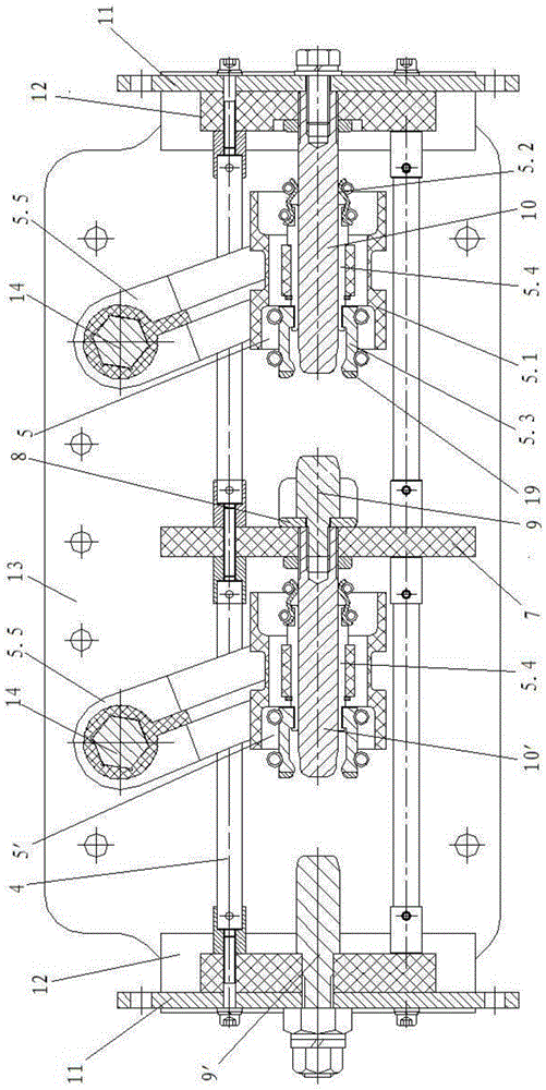
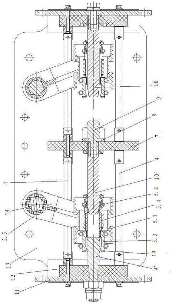
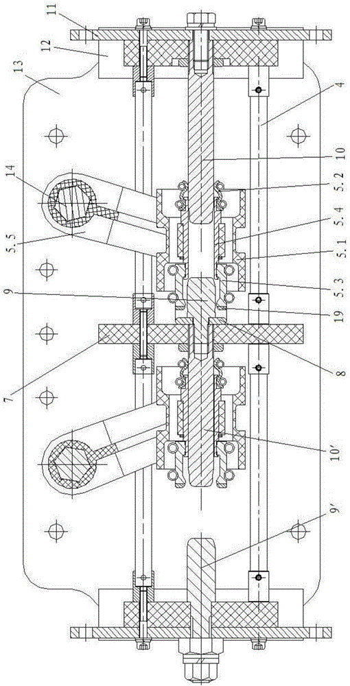
[0042] Such as Figure 1-3 As shown: the switch in this embodiment includes an output copper bar 8, an intermediate insulating mounting plate 7, a closing switch on the left and a closing switch on the right.

[0043] The output copper bar 8 in the switch of this embodiment is connected to the intermediate insulating mounting plate 7; the closing switch on the left side and the closing switch on the right side are arranged on the left and right sides of the switch bracket body 13 at the same time, and the closing switch on the left side The gate switch and the closing switch on the right side are located on both sides of the intermediate insulating mounting plate 7 .

[0044] The closing switches on the right side all include a main shaft 14 , an insulating mounting plate 12 , a connecting copper bar 11 , a first static contact 10 , a movable electrode assembly ...

Embodiment 2

[0059] In this embodiment, taking the grounding switch of the bidirectional automatic switching ring network equipment composed of three switches as an example, its structure and working process are further described. Such as Figure 4 , Figure 5 and Figure 6 shown.

[0060] The load switch in this embodiment is formed by connecting three switches in Embodiment 1 in series. For the specific structure and working process of the switch, refer to the description in Embodiment 1.

[0061] In this embodiment, the left closing switch in the grounding switch and the right closing switch in the grounding switch respectively share the same main shaft 14 .

[0062] In this embodiment, the output copper bar 8 in the grounding switch is a grounding copper bar, and is connected to the switch bracket body 13 . Observation windows 13.1 are provided on both side plates of the switch bracket body 13 . The grounding switch is designed with observation windows on both sides of the switch...


PUM


Abstract

The invention discloses a switch and a bidirectional automatic-switching looped network equipment earthing switch comprising the same. The problems to be solved are that an earthing switch of an existing product is of two independent switches which are not integrated, and a switch blade contact mode is mainly adopted, so that the earthing switch is complex to process and assemble; the two switches are not interlocked, so that the possibility of misoperation is increased relatively. The technical scheme includes that the switch comprises an output copper bar, a middle insulated mounting plate, a left switch-on switch and a right switch-on switch; each of the left switch-on switch and the right switch-on switch comprises a main shaft, an insulated mounting plate, a connecting copper bar, a first fixed contact, a movable electrode component and a second fixed contact. The bidirectional automatic-switching looped network equipment earthing switch is formed by series connection of three switches.

Description

technical field [0001] The invention relates to a switch, and also relates to a grounding switch for bidirectional automatic switching ring network equipment formed by three switches connected in series. Background technique [0002] At present, the grounding switch of the existing product is two independent switches, which are not integrated. The main reason is that the contact type of the knife blade exists, the processing and assembly are complicated, and there is no interlock between the two, so the probability of misoperation occurs. Relatively improved. [0003] The grounding switch with the traditional blade contact, the surface of the blade will be uneven, or the angle will deviate, which will lead to poor contact and high resistance, which will cause a lot of heat on the contact surface and cause safety accidents. Contents of the invention [0004] The technical problem to be solved by the present invention is: the grounding switch of the existing product is two ...

Claims


Application Information

Patent Timeline
Patent Type & Authority Applications(China)
IPC IPC(8): H01H9/26H01H1/50H01H9/30
CPCH01H1/50H01H9/02H01H9/26H01H9/30H01H2009/0292
Inventor 韩良春林涛奚庆博毕云锋穆双申纬黄滨波
Owner WUXI VITZRO ELECTROMECHANICAL
Learn More