
Rapid cable fixing device

A fixing device and cable technology, applied in the direction of electrical components, etc., can solve the problems of large wall damage area, easy loosening of cables, high cost, etc., and achieve the effect of small wall area, good clamping effect and long service life

Inactive Publication Date: 2015-03-11
STATE GRID CORP OF CHINA +3
View PDF11 Cites 6 Cited by
  • Summary
  • Abstract
  • Description
  • Claims
  • Application Information

AI Technical Summary

Problems solved by technology

[0002] At present, when the cable needs to be fixed on the wall or the cabinet wall, or the cable needs to be fixed at the corner, it is usually fixed by bundling. The disadvantage of this fixing method is that the operation is cumbersome, and the cable is easy to loosen. It is not easy to control the binding force on the cable, and it is easy to cause damage to the cable
The patent document whose application number is 201310465811.4 discloses a fast fixing device for cables, but the above-mentioned fixing device has the following disadvantages: 1. The shrapnel is fixed in the frame body. Because the diameter of the cable is not fixed, the shrapnel is easily deformed under the action of the bolt. Too large and damaged; 2. The shrapnel is fixed in the frame body. If the shrapnel damages the whole device, it cannot be used, and the cost is high; 3. The clamped cable directly acts on the wall, and the damage area to the wall is large.

Method used


Image

  • Rapid cable fixing device
  • Rapid cable fixing device
  • Rapid cable fixing device

Examples


Embodiment Construction

[0013] The technical solutions in the embodiments of the present invention are clearly and completely described below in conjunction with the accompanying drawings in the embodiments of the present invention. Obviously, the described embodiments are only part of the embodiments of the present invention, not all of them. Based on the embodiments of the present invention, all other embodiments obtained by persons of ordinary skill in the art without making creative efforts belong to the protection scope of the present invention.

[0014] In the following description, a lot of specific details are set forth in order to fully understand the present invention, but the present invention can also be implemented in other ways different from those described here, and those skilled in the art can do it without departing from the meaning of the present invention. By analogy, the present invention is therefore not limited to the specific examples disclosed below.

[0015] Such as Figure...


PUM


Abstract

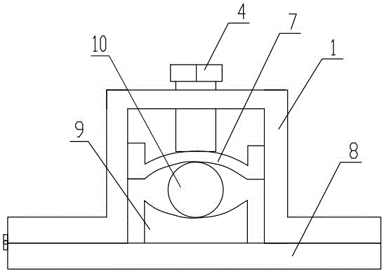
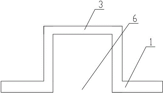
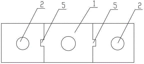
The invention discloses a rapid cable fixing device and relates to the technical field of devices for mounting cables or wires on the surface or in the interior of a building. The fixing device comprises a metal framework shaped like a Chinese character ji, wherein grooves are formed in the left and right side walls of the interior of the projection, the two ends of an arc-shaped plate are positioned in the grooves, the arc-shaped plate can slide up and down along the grooves, a metal plate is arranged at the opening part, the metal plate is a straight plate, one end of the metal plate is connected with a side shaft on the left side or the right side of the metal framework shaped like the Chinese character ji, via holes corresponding to fixing holes are formed in the left and right two sides of the metal plate, the other end of the metal plate is a free end, and the curvature radius of the arc-shaped plate is larger than the radius of a clamped cable. The fixing device has the characteristics of long service life, great fixing effect and low maintenance cost.

Description

technical field [0001] The invention relates to the technical field of devices for installing cables or wires on or inside buildings, in particular to a fast fixing device for cables. Background technique [0002] At present, when the cable needs to be fixed on the wall or the cabinet wall, or the cable needs to be fixed at the corner, it is usually fixed by bundling. The disadvantage of this fixing method is that the operation is cumbersome, and the cable is easy to loosen. It is not easy to control the binding force on the cable, which is easy to cause damage to the cable. The patent document whose application number is 201310465811.4 discloses a fast fixing device for cables, but the above-mentioned fixing device has the following disadvantages: 1. The shrapnel is fixed in the frame body. Because the diameter of the cable is not fixed, the shrapnel is easily deformed under the action of the bolt. Two, the shrapnel is fixed in the frame body, if the shrapnel damages the w...

Claims


Application Information

Patent Timeline
IPC IPC(8): H02G3/30
Inventor 叶孝祖
Owner STATE GRID CORP OF CHINA
Learn More