Device for measuring gas transmission rate of thin film according to resistivity method and manufacturing and testing method thereof

A technology of gas transmission rate and electrical resistance method, which is applied in the direction of measuring device, permeability/surface area analysis, suspension and porous material analysis, etc., can solve the problem of high background noise value, achieve low background noise value, less molecular adsorption, The effect of small total area

Pending Publication Date: 2019-04-30
SUN YAT SEN UNIV
View PDF0 Cites 1 Cited by
  • Summary
  • Abstract
  • Description
  • Claims
  • Application Information

AI Technical Summary

Problems solved by technology

[0010] In view of the high background noise value of the current gas transmission rate instrument, which can only test one kind of gas, and the edge penetration of the independent membrane test, the present invention provides a device for measuring the gas transmission rate of a thin film by resistance method and its production and testing method. The invention has the advantages of low background noise, high measurement accuracy, can test a variety of gases, can accelerate aging, and has the advantages of low cost

Method used


Image

  • Device for measuring gas transmission rate of thin film according to resistivity method and manufacturing and testing method thereof
  • Device for measuring gas transmission rate of thin film according to resistivity method and manufacturing and testing method thereof
  • Device for measuring gas transmission rate of thin film according to resistivity method and manufacturing and testing method thereof

Examples


Embodiment 1

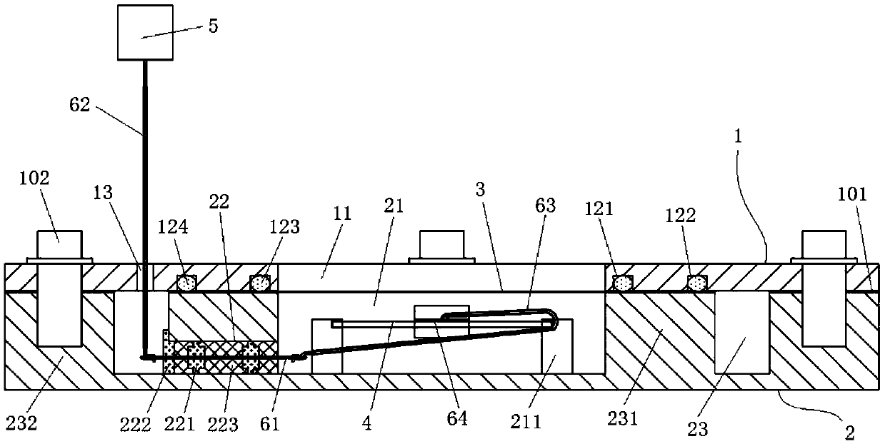
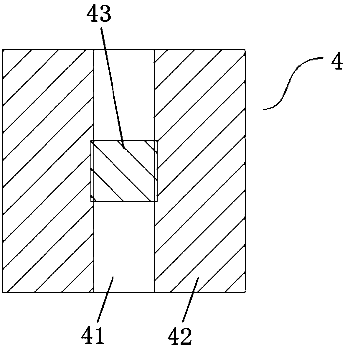
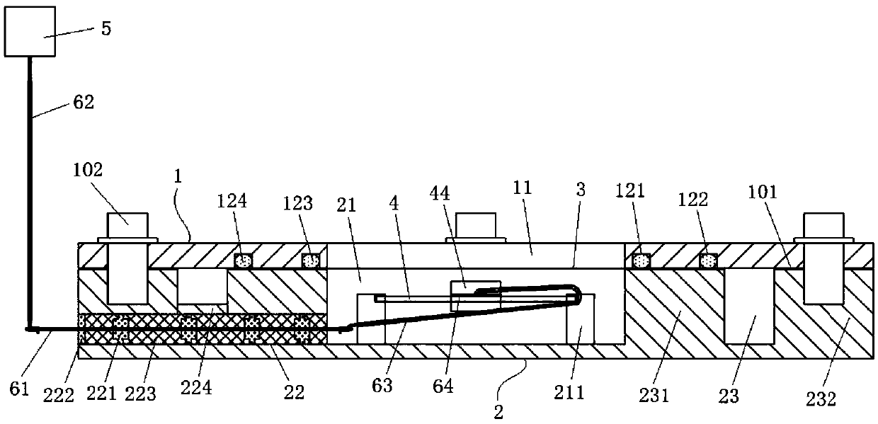
[0063] A device for testing the gas permeability of thin films by resistance method in this embodiment is as follows: figure 1 shown. A chamber 21 is provided in the lower cavity 2, and a lead hole 22 for the hard wire 61 to pass is provided on the side wall of the chamber 21. After the hard wire 61 passes through the lead hole 22, the lead hole 22 is made of glass or ceramic material gas. The airtight potting body 223 is potted. There is a resistance detection sample piece 4 in the chamber 21 ; the hard wire 61 is connected to the second soft wire 63 with an insulating layer in the chamber 21 , and is connected to the lead-out electrode 42 of the active metal 43 through the electrode patch 64 . The hard wire 61 is connected to the first flexible wire 62 with an insulating layer in the surrounding chamber 23 , and the lead-out testing device is connected to the resistance measuring meter 5 . The upper cover body 1 is provided with a hole 11 corresponding to the position of t...

Embodiment 2

[0075] In this embodiment, the thin film 3 is made of aluminum foil (Mocon Co., USA), and the permeation amount in the Z direction is zero, so the damage of the active metal is entirely due to the edge permeation in the XY direction. Here, the actual sealing effect of the test device will be described in combination with experimental data. The better the sealing effect is, the more difficult it is for the active metal to be damaged by external water and oxygen to maintain a stable resistance value. On the contrary, the active metal is damaged and the resistance increases until it is insulated.

[0076] The device components used for the test were vacuum-dried at 80°C for 12 hours, and then transferred to a glove box. The water and oxygen content of the glove box was kept below 0.01ppm. The resistance detection sample piece 4 with the ITO lead-out electrode 42 is placed on the mask plate, and a layer of metallic calcium is vapor-deposited under high vacuum conditions in the PVD...

Embodiment 3

[0088] As mentioned earlier, film 3 uses aluminum foil, which has zero penetration in the Z direction, and the damage to the active metal is entirely due to edge penetration in the XY direction. Because aluminum foil can completely block water and oxygen molecules in the Z direction, it is used for the independent zero value (individual zero) collection of Mocon water permeability test equipment, that is, there is no transmission in the direction of the cavity, and machine noise is collected. The purpose of using this aluminum foil in this embodiment is to understand the edge sealing effect and determine the background noise value of the test device.

[0089] The preferred sealing structure that provides according to embodiment 2 assembles inner seal ring 123, outer seal ring 124, sealant 101, places film 3, surrounds chamber 23 and fills absorbent (8Fe / 2P 2 o 5 ); take out the test device from the glove box, place it in an air environment for testing (25° C., 65% RH), and re...


PUM

PropertyMeasurementUnit
thicknessaaaaaaaaaa
electrical resistanceaaaaaaaaaa

Abstract

The invention discloses a device for measuring the gas transmission rate of a thin film, which comprises a lower cavity and an upper cover body, wherein the lower cavity is provided with a chamber, the wall of the chamber is provided with a wire leading hole provided for a wire to pass through, and the wire leading hole is filled and sealed in by a glass or ceramic material in an airtight manner after the wire passes through the wire leading hole; the chamber is internally provided with a resistance detection sample sheet; one end of the wire is directly or indirectly connected with an activemetal layer, and the other end is connected to a resistance meter; the upper cover body is provided with a hole at the position corresponding to the chamber, a soft sealing structure is arranged around the hole in the direction facing towards the lower cavity, and the thin film to be detected is clamped between the upper end face of the chamber wall of the lower cavity and the upper cover body. The device has the advantages of low cost, ability of testing various gases, low background noise, high measurement accuracy and ability of accelerating aging.

Description

technical field [0001] The invention belongs to the technical field of gas transmission rate testing, and in particular relates to a device for testing the gas transmission rate of a thin film and a manufacturing and testing method thereof. Background technique [0002] In organic light emitting diode (OLED) devices, in order to improve electron injection efficiency, metals with low work function (low work function) are usually used as cathode materials. The work function refers to the minimum energy required to move an electron from the interior of a solid to the surface of the object. Therefore, metals with low work functions have higher mobility, that is, active metals. Materials commonly used as OLED cathodes include calcium, magnesium, etc. These active metals are easy to react with oxygen and water in the air and fail, so they must be protected. In order to enable OLED devices to achieve a ten-year service life, it is generally required that the water vapor transmissi...

Claims


Application Information

Patent Timeline
Patent Type & Authority Applications(China)
IPC IPC(8): G01N15/08
CPCG01N15/0806
Inventor 张艺朱龙基余桥溪刘腾梁绍森蒋星杨伯儒许家瑞池振国刘四委
Owner SUN YAT SEN UNIV
Why Eureka
Try Eureka