

Clamping and positioning device for instrument head flanging
A technology of clamping, positioning and flanging, which is applied to positioning devices, feeding devices, storage devices, etc., can solve the problems of complex structure of clamping and positioning devices, inconvenient to popularize and use, affecting processing quality, etc. Simple, good clamping effect
- Summary
- Abstract
- Description
- Claims
- Application Information
AI Technical Summary
Problems solved by technology
Method used
Image

Examples
Embodiment 1
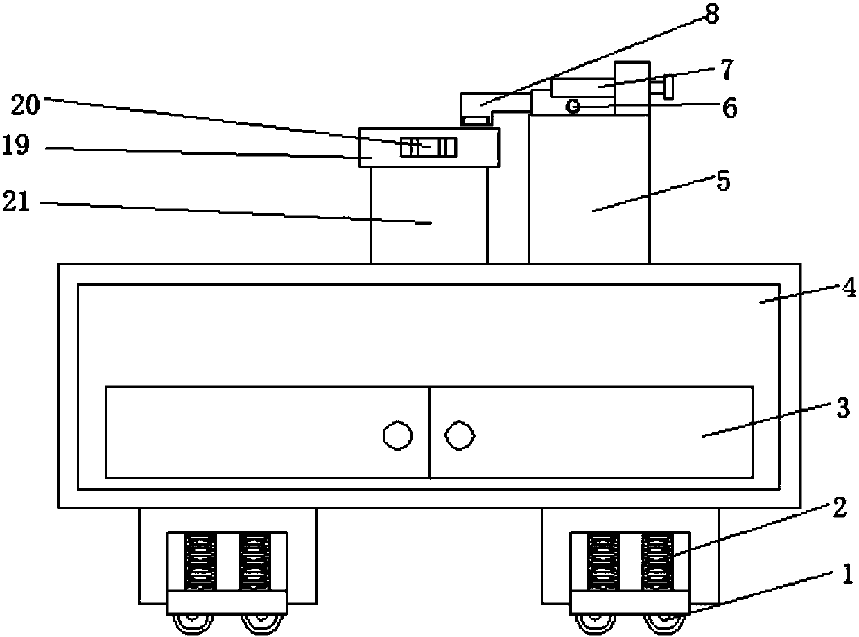
[0020] Embodiment 1: with reference to Figure 1-2 , a clamping and positioning device for the flange of the meter head, including a base 4, a storage device 3 is arranged on the base 4, the storage device 3 includes two storage chambers, each storage chamber is rotatably connected with a revolving door, The revolving door is fixedly connected with a pull handle by bolts, which is convenient for placing some tools in the storage cavity, and is convenient for taking during work. One side of the base 4 is provided with a shock absorbing device 2 and a moving device 1, and the shock absorbing device 2 includes a support The support plate is provided with a first groove, and two spring rods are symmetrically arranged on the inner wall of the first groove, and one end of the spring rod is fixedly connected to the buffer block. Through the interaction of the spring rod and the buffer block and other structures, it can Slow down part of the impact force to play the role of shock abso...
Embodiment 2
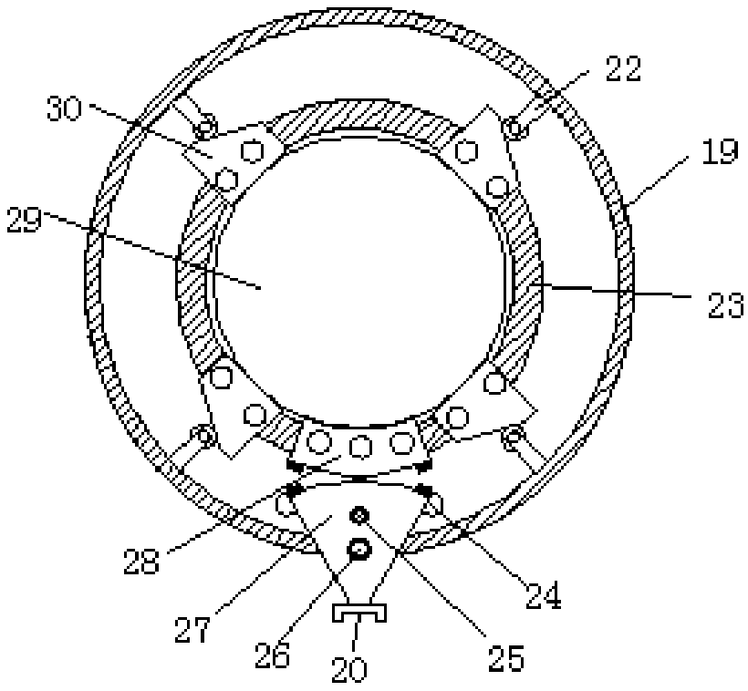
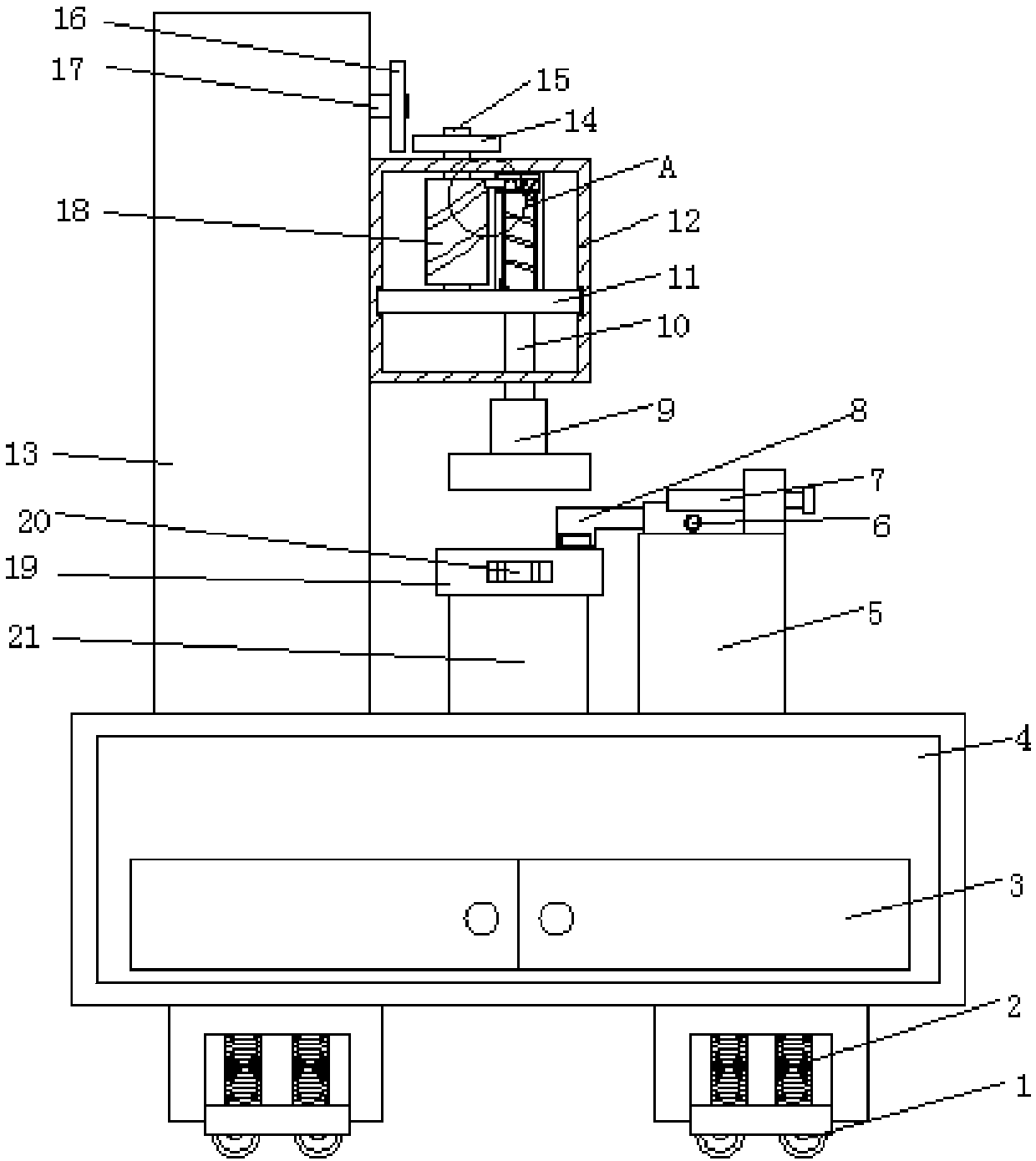
[0021] Embodiment 2: refer to Figure 2-4, applying the present invention to a watch head flanging device, comprising a base 4, the base 4 is provided with a storage device 3, the storage device 3 includes two storage chambers, each storage chamber is connected with a rotating door for rotation, The door is fixedly connected with a pull handle by bolts, which is convenient for placing some tools in the storage cavity and being easy to take during work. One side of the base 4 is provided with a shock absorbing device 2 and a moving device 1, and the shock absorbing device 2 includes a support plate , the support plate is provided with a first groove, and two spring rods are symmetrically arranged on the inner wall of the first groove, and one end of the spring rod is fixedly connected to the buffer block, and the interaction between the spring rod and the buffer block can slow down Part of the impact force plays the role of shock absorption. The mobile device 1 includes a plura...
PUM
 Abstract
Description
Claims
Application Information