Supercharge Your Innovation With Domain-Expert AI Agents!

Structure device for zoning vibration of dust collecting plate

A technology of dust collector and separator, applied in the direction of electrode structure, electrostatic separation, etc.

Inactive Publication Date: 2015-03-18
上海冶金矿山机械厂
View PDF5 Cites 0 Cited by
  • Summary
  • Abstract
  • Description
  • Claims
  • Application Information

AI Technical Summary

Problems solved by technology

The smaller the dust particles, the more obvious this phenomenon is, which becomes a major difficulty in improving the dust removal efficiency
Especially in the last electric field, after the dust enters the flue gas again, it is directly discharged out of the dust collector, which is a problem that cannot be fundamentally solved by the existing structure

Method used


Image

  • Structure device for zoning vibration of dust collecting plate
  • Structure device for zoning vibration of dust collecting plate

Examples


Embodiment Construction

[0010] Below in conjunction with accompanying drawing and specific embodiment the present invention is described in further detail:

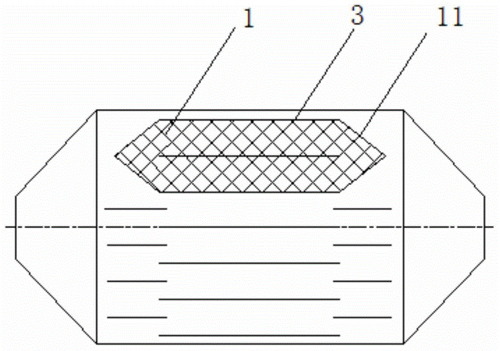
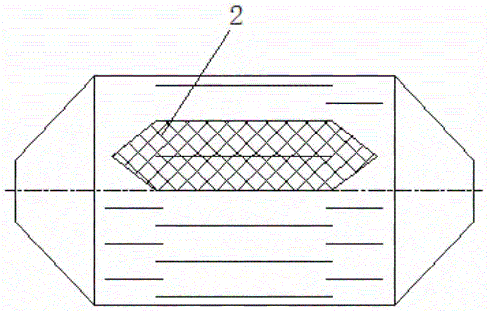
[0011] Depend on figure 1 , figure 2 It can be seen that the present invention includes: the front end 1 of the electric field and the rear end 2 of the electric field; a set of air flow baffles (11, 21) are arranged respectively at the front end 1 of the electric field and the rear end 2 of the electric field; the top of the set of air flow baffles is placed There is a mechanism (not shown in the figure) that drives the partition to rotate; through the rotation of the group of airflow partitions, it cooperates with the dust collecting plate 3 to form an isolation partition in the flue gas.

[0012] In the present invention, a group of airflow baffles are respectively arranged at the front end and the rear end of the electric field, and a mechanism for driving the baffles to rotate is arranged on the top. Utilize the rotation of the airflow b...


PUM


Abstract

The invention discloses a structure device for zoning vibration of a dust collecting plate. The structure comprises an electric field front end and an electric field rear end, wherein the electric field front end and the electric field rear end are respectively provided with one group of airflow baffle plates; a mechanism for driving the baffle plats to rotate is arranged at the top of the one group of airflow baffle plates; the airflow baffle plates are matched with the dust collecting plate to form an isolating region in smoke by virtue of rotation of the one group of airflow baffle plates. The structure device has the beneficial effects that by combining top electromagnetic vibration, at the front end of an electric field at the rear part of a dust remover, the airflow baffles are kept in parallel with anode plates when not used by arranging one group of corresponding airflow baffle plates, and are pairwise closed according to an order when in use, and one group of anode plates in the electric field are separated in the smoke; falling dust can not enter the smoke again during vibration; because the vibration period of the electric field at the rear part is long, the structure device is only used for isolating one group of polar plates in the electric field, and ensures that the influence of closing the baffle plates on the airflow in the dust remover is minimized through CFD simulation.

Description

technical field [0001] The invention relates to an electric dust collector, in particular to a dust collecting plate structure device of the electric dust collector. Background technique [0002] Thermal power installed capacity accounts for more than 80% of my country's installed power generation capacity, and thermal power units are mainly coal-fired. Nowadays, environmental protection requirements are becoming increasingly stringent. In order to control the emission of air pollutants from coal-fired power plants, the National Environmental Protection Agency has formulated a 30mg / m 3 new emission standards. The original design of the electrostatic precipitator has become more and more difficult to meet the existing standards, so the structure of the electrostatic precipitator needs to be improved. [0003] In the dust collector, the closer to the electric field at the back, the smaller the collected dust particles, and the more difficult it is to rap, even if the rapping ...

Claims


Application Information

Patent Timeline
IPC IPC(8): B03C3/47
Inventor 毛一玮
Owner 上海冶金矿山机械厂
Features
  • R&D
  • Intellectual Property
  • Life Sciences
  • Materials
  • Tech Scout
  • Unparalleled Data Quality
  • Higher Quality Content
  • 60% Fewer Hallucinations
Learn More