
Numerical control machining center air source automatic water distribution filter

A machining center and air source technology, which is applied in the field of automatic water-separating water filters for air sources in CNC machining centers, can solve the problems of troublesome cleaning and drainage, poor water filtering effect, etc., and achieves reduced labor intensity, good filtering effect, and easy use. Effect

Active Publication Date: 2021-08-24
安徽津野数控科技有限公司
View PDF5 Cites 0 Cited by
  • Summary
  • Abstract
  • Description
  • Claims
  • Application Information

AI Technical Summary

Problems solved by technology

[0005] The purpose of the present invention is to solve the problems of poor water filtration effect, frequent manual cleaning and drainage of the filter element, and to provide an automatic air source for a CNC machining center with good water filtration effect, automatic cleaning of the filter element, and convenient drainage. water filter

Method used


Image

  • Numerical control machining center air source automatic water distribution filter
  • Numerical control machining center air source automatic water distribution filter
  • Numerical control machining center air source automatic water distribution filter

Examples


Embodiment 1

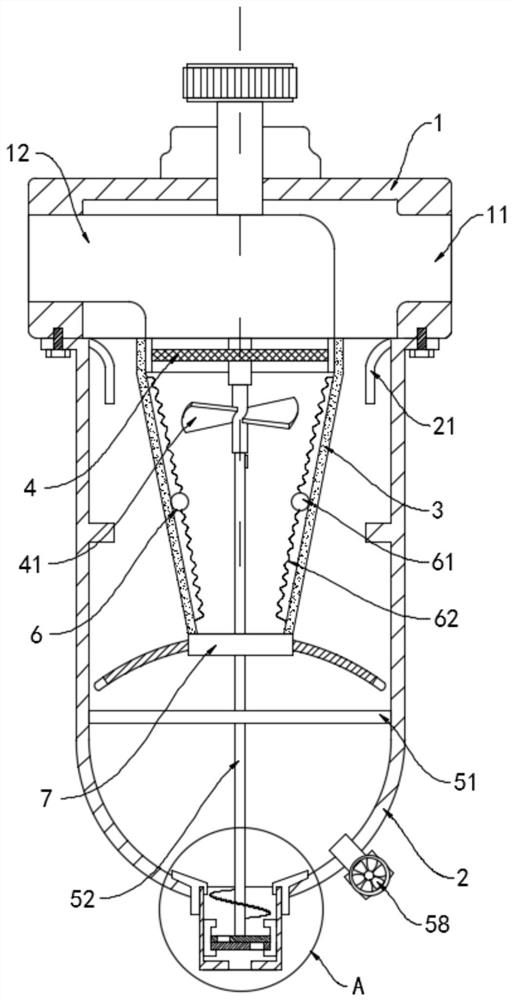
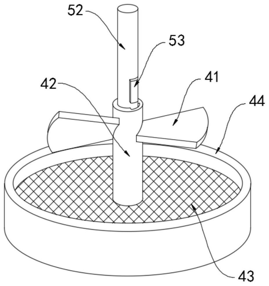
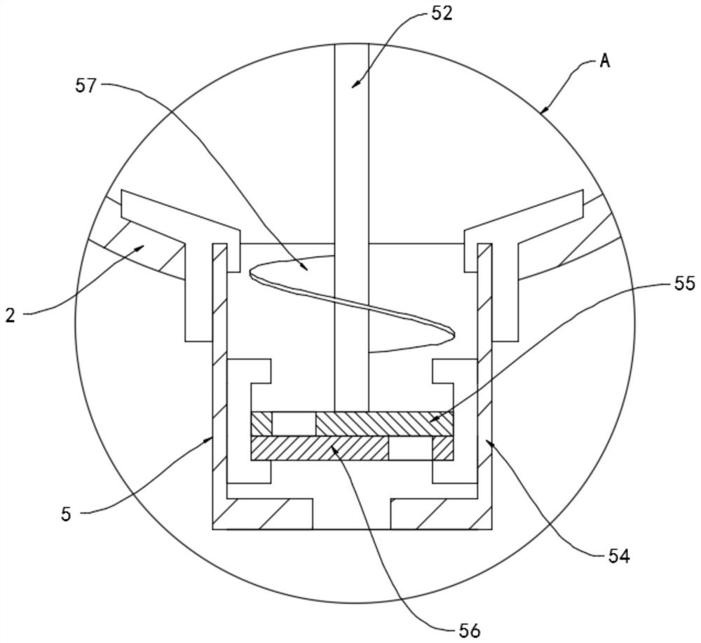
[0028] Refer to attached figure 1 , an air source automatic water separation water filter for a CNC machining center, comprising a main body 1, an air inlet 11, an air outlet 12, a water cup 2, a deflector 21 and a filter element 3, and the side walls on both sides of the main body 1 are relatively arranged There is an air inlet 11 and an air outlet 12, the lower end of the main body 1 is equipped with a water cup 2, the inner wall of the upper opening of the water cup 2 is provided with a deflector 21, the inner end of the air inlet 11 communicates with the upper opening of the water cup 2, The water cup 2 is provided with a filter element 3, the inner end of the air outlet 12 is fixedly connected with the upper end opening of the filter element 3, the upper end of the filter element 3 is provided with a filter mechanism 4, and the bottom of the water cup 2 is equipped with a buoyancy drainage mechanism 5;

[0029] Refer to attached Figure 1-2 Specifically, the filter mecha...

Embodiment 2

[0045] Refer to attached Figure 5 The difference between this embodiment and Embodiment 1 is that the filter screen plate 43 is arranged in the shape of a spiral blade, and the filter screen plate 43 is evenly extended and coiled around the axis of the drum 42, and the inner ring side wall of the collar 44 is ring-shaped. There are many diversion grooves 8 arranged in an array, and the plurality of diversion grooves 8 are all vertically arranged. The horizontal section of the diversion grooves 8 is an isosceles trapezoidal setting, and the opening of the diversion grooves 8 near the screen plate 43 side is relatively small. Small.

[0046] In this embodiment, every time the wind wheel 41 rotates one turn, the spiral blade-shaped filter screen plate 43 can sweep over every place in the inner space of the collar 44, which improves the resistance of the filter screen plate 43 to the water vapor and water vapor in the compressed air. The ability to capture impurities further imp...


PUM


Abstract

The invention belongs to the field of numerical control machining equipment, and particularly relates to a numerical control machining center air source automatic water distribution filter which comprises a main body, an air inlet, an air outlet, a water cup, a flow guide plate and a filter element, the air inlet and the air outlet are oppositely formed in the side walls of the two sides of the main body, and the water cup is installed at the lower end of the main body; a flow guide plate is arranged on the inner wall of an opening in the upper end of the water cup, the inner end of the air inlet communicates with the opening in the upper end of the water cup, a filter element is arranged in the water cup, the inner end of the air outlet fixedly communicates with an opening in the upper end of the filter element, a filtering mechanism is arranged at the upper end of the filter element, and a buoyancy drainage mechanism is installed at the bottom of the water cup; and the filtering mechanism comprises a pneumatic wheel, a rotary drum, a filter screen plate and a lantern ring, and the lantern ring is fixedly connected to the inner side wall of the upper end of the filter element. The water filtering effect is good, the filter element is automatically cleaned, the blocking problem is avoided, water can be automatically drained while water filtering work is carried out, continuous work is not affected, and the work efficiency is improved.

Description

technical field [0001] The invention belongs to the field of numerical control processing equipment, and in particular relates to an air source automatic water separation filter for a numerical control processing center. Background technique [0002] In the CNC machining center, it is necessary to separate the water vapor, oil droplets and other impurities in the compressed gas from the gas through the automatic water separation filter to achieve the function of purifying the gas source, so as to ensure the normal operation of the pneumatic actuator. The pressure reducing valve and the lubricator are used together. The component that integrates these three is called the air source triplet. The air source triplet dries the compressed gas, adjusts the pressure and refuels, which protects the pneumatic actuator well. [0003] After searching, the national patent publication number is CN 207694440 U3, which discloses the decompression oil-water separation structure in the air so...

Claims


Application Information

Patent Timeline
Patent Type & Authority Applications(China)
IPC IPC(8): B01D50/00B01D53/24B01D53/26
CPCB01D53/24B01D53/26B01D53/266B01D50/20
Inventor 王诗豪凌川生
Owner 安徽津野数控科技有限公司
Learn More