Clamping mechanism for blanking machine

A clamping mechanism and blanking technology, applied in metal processing equipment, feeding devices, manufacturing tools, etc., can solve the problems of poor stability of the clamping mechanism, improve work efficiency, stable and efficient processing, and ensure clamping reliability Effect

Inactive Publication Date: 2015-03-18
熊凌聪
View PDF0 Cites 4 Cited by
  • Summary
  • Abstract
  • Description
  • Claims
  • Application Information

AI Technical Summary

Problems solved by technology

[0004] The invention solves the problem of poor stability of the traditional clamping mechanism by setting the clamping mechanism of the blanking machine, so as to achieve the purpose of stable and efficient processing

Method used


Image

  • Clamping mechanism for blanking machine

Examples


Embodiment 1

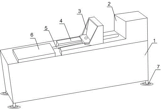
[0019] Such as figure 1 As shown, this embodiment includes a clamping unit, a guide rail 4 and a fixed frame 1, the guide rail 4 and the clamping unit are placed on the fixed frame 1, the clamping unit includes a movable baffle 3 and a fixed baffle 2, and the movable baffle The plate 3 is slidably arranged on the guide rail 4 , the fixed baffle 2 is arranged on the fixed frame 1 , and also includes a hydraulic mechanism, and the hydraulic mechanism is connected with the bottom end of the movable baffle 3 . On the fixed frame 1, the movable baffle 3 and the fixed baffle 2 form a clamping unit that can change the clamping gap according to the size of the workpiece. The fixed baffle 2 can limit the workpiece, and the movable baffle 3. Under the push of the hydraulic mechanism, the workpiece can be quickly advanced and retreated to clamp or loosen; during the material cutting process, the workpiece is close to the inner wall of the fixed baffle 2, and the movable baffle 3 is pushe...

Embodiment 2

[0021] Such as figure 1 As shown, the present embodiment is based on Embodiment 1, the hydraulic mechanism includes a hydraulic cylinder 6 and a hydraulic motor, the hydraulic cylinder 6 is arranged on the same level as the movable baffle 3, the guide rail 4 is a U-shaped groove, and the hydraulic cylinder One end of the output end 5 passing through the U-shaped groove is connected to the bottom end of the movable baffle 3 , and the other end of the U-shaped groove is connected to the fixed baffle 2 . In view of defects such as unstable clamping of mechanical clamping and easy noise generation of pneumatic clamping, on the same horizontal plane, the hydraulic motor converts hydraulic energy into mechanical energy output, and the output end 5 of the hydraulic cylinder drives the movable baffle 3 to maintain a stable and fast speed. Back-and-forth linear motion works; the movable baffle 3 is slidably arranged on the U-shaped groove, and the opening of the U-shaped groove can be ...

Embodiment 3

[0023] Such as figure 1 As shown, on the basis of Embodiment 1, this embodiment also includes a plurality of studs arranged on the side of the movable baffle 3 facing the fixed baffle 2 and a plurality of shockproof feet 7 arranged at the bottom of the fixed frame 1 . During the clamping process, in order to better ensure the clamping efficiency, the studs set on the inner wall of the movable baffle 3 can engage the workpiece, increase the friction between the movable baffle 3 and the workpiece, and avoid the cutting mechanism when cutting. cause mutual collision between the workpiece and the baffle; when cutting, a large interaction force will be generated between the cutting mechanism and the workpiece, between the workpiece and the fixed frame 1, and the anti-vibration pad 7 arranged at the bottom of the fixed frame 1 can The resulting interaction force is offset to further protect the clamping mechanism and prolong its service life.


PUM


Abstract

The invention discloses a clamping mechanism for a blanking machine. The clamping mechanism comprises a clamping unit, a guide rail and a fixing frame, wherein the guide rail and the clamping unit are respectively arranged on the fixing frame, the clamping unit comprises a movable baffle plate and a fixed baffle plate, the movable baffle plate is glidingly arranged on the guide rail, the fixed baffle plate is arranged on the fixing frame, the clamping mechanism also comprises a hydraulic mechanism, and the hydraulic mechanism is connected with the bottom end of the movable baffle plate. During the material cutting work procedure, a workpiece is tightly attached to the inner wall of the fixed baffle plate, the movable baffle plate approaches to the fixed baffle plate under push by the output end of the hydraulic mechanism until the workpiece is tightly clamped, and finally, a cutting mechanism is used for carrying out cutting processing on the workpiece. The hydraulic mechanism is adopted, the problems of clamping instability of conventional machinery and great noise generated by the clamping of a pneumatic clamping mechanism are solved, the clamping reliability is ensured, meanwhile, good operation environment is also maintained, and the work efficiency is improved.

Description

technical field [0001] The invention relates to the field of mechanical processing, in particular to a clamping mechanism of a blanking machine. Background technique [0002] The cutting machine is an indispensable equipment in some light industries. It is a machine that cuts and processes materials by pressing the knife mold with the force of machine movement. According to the structure, it can be divided into rocker type blanking machine, the punching part is a swingable rocker arm, which is suitable for punching natural materials; gantry type blanking machine, the punching part is a punching part that can move left and right along the beam The knife die can be fixed on the punching head or placed on the workpiece. The punch head of the large-scale computer-controlled gantry blanking machine is equipped with a rotatable knife die holder, which can be selected according to the program typesetting. Knife; flat-bed blanking machine, the difference between it and the gantry-t...

Claims


Application Information

Patent Timeline
Patent Type & Authority Applications(China)
IPC IPC(8): B21D43/00B21D28/02
CPCB21D28/04B21D28/02
Inventor 熊凌聪
Owner 熊凌聪
Why Eureka
Try Eureka