
Hose attaching structure

A technology for installing structures and hoses, which is applied to hose connecting devices, pipes/pipe joints/fittings, components of pumping devices for elastic fluids, etc. It can achieve the effect of easy position alignment, realization of position alignment, and prevention of biting

Inactive Publication Date: 2015-03-18
HONDA MOTOR CO LTD
View PDF11 Cites 0 Cited by
  • Summary
  • Abstract
  • Description
  • Claims
  • Application Information

AI Technical Summary

Problems solved by technology

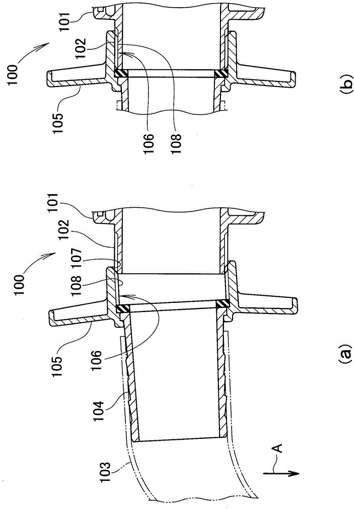
[0004] However, when the hose joint in the state where the hose is attached is screwed to the suction port of the water pump, the hose joint is inclined due to the weight of the hose, and the threaded parts are not easy to engage with each other.
Therefore, it is difficult to align the hose joint horizontally with the suction port to properly tighten the threaded portion
There is room for improvement in terms of screwing the hose joint with the hose attached to the suction port of the water pump

Method used


Image

  • Hose attaching structure
  • Hose attaching structure
  • Hose attaching structure

Examples


Embodiment

[0018] First, the working machine according to the embodiment will be described.

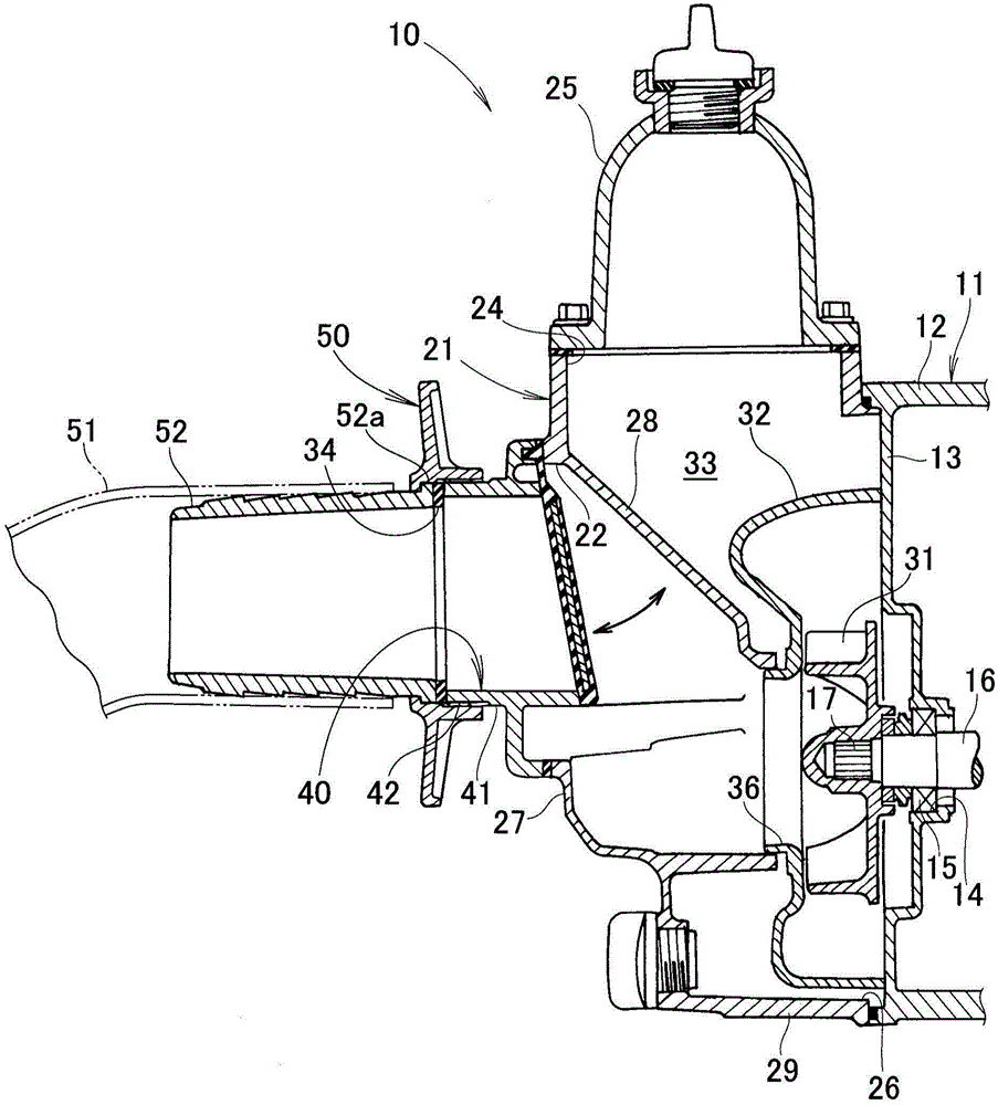
[0019] Such as figure 1 Shown; working device 10 is, for example, a water pump. The water pump 10 has: an engine 11; a housing 21 provided on the cylinder block 12 of the engine 11; a suction nozzle 40 provided on the suction port 22 of the housing 21; and a discharge nozzle 25 provided at the outlet 24 of the housing 21.

[0020] The engine 11 has: a partition wall 13 of the cylinder block 12 ; a mechanical seal 15 provided in a support hole 14 of the partition wall 13 ; and a crankshaft 16 provided rotatably on the mechanical seal 15 . An end portion 17 of the crankshaft 16 protrudes into the housing 21 , and the impeller 31 is connected to the end portion 17 .

[0021] The volute 32 is arranged in the housing 21 , and the impeller 31 is covered by the volute 32 . The opening 26 of the casing 21 is closed by the partition wall 13 , and the volute 32 is provided on the partition wall 13 , w...


PUM


Abstract

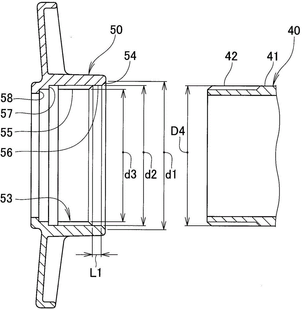
An annular hose coupling is connected to a hose nipple having a hose attached thereto. The hose coupling has, on its inner peripheral surface, a non-threaded portion and a female threaded portion to be screwed onto a male threaded portion formed on a distal end portion of a suction nozzle. The non-threaded portion is located on a distal end portion of the hose coupling to be inserted over the nozzle and having such an inner diameter that the non-threaded portion is fittable over the male threaded portion of the nozzle. The hose coupling is connected to the nozzle through meshing engagement between the female threaded portion of the hose coupling and the male threaded portion of the nozzle.

Description

technical field [0001] The present invention relates to an improvement of a hose mounting structure for mounting a hose to a working device. Background technique [0002] As a hose attachment structure for attaching a hose to a working device such as a water pump, a structure in which a hose is attached to the water pump via a hose joint is known. Among the hose joints, there are structures that are attached to the water pump with claws, or structures that are attached to the water pump with threads. As such a hose mounting structure, for example, the technology described in the following Patent Document 1 is known (for example, refer to Patent Document 1 ( figure 1 ). ). [0003] The hose attachment structure shown in this patent document 1 is a structure in which a hose is attached to the suction port formed along the horizontal direction of a water pump. A female thread portion is formed at the suction port of the water pump, and an external thread portion is formed a...

Claims


Application Information

Patent Timeline
Patent Type & Authority Applications(China)
IPC IPC(8): F04D29/00
CPCF16L15/00F04D29/406F04D29/605F16L19/025F16L33/30F04B1/0452
Inventor 宫原一嘉冈部格
Owner HONDA MOTOR CO LTD
Learn More