Sealing components and sealing systems of nuclear power plant generators

A sealing system and sealing component technology, applied in the field of nuclear power plants, can solve the problem that the number of times of oil blocking and buffer discharge of oil cannot reach the application occasion, the number of oil teeth can not be increased, the number of oil grooves can not be increased, and the oil blocking effect can not meet the requirements Requirements and other issues, to achieve the effect of improving the sealing oil blocking effect, increasing the number of blocking times, and reducing the amount of oil

Active Publication Date: 2017-11-21
CHINA GENERAL NUCLEAR POWER CORP +1
View PDF9 Cites 0 Cited by
  • Summary
  • Abstract
  • Description
  • Claims
  • Application Information

AI Technical Summary

Problems solved by technology

[0006] One is to increase the number of sealing rings to achieve the purpose of increasing the number of oil teeth used to block the sliding of lubricating oil. However, due to the limited axial width of the inner oil retaining ring along the rotating shaft, an inner oil retaining ring At most two sealing rings can be installed on the top, so that the number of oil teeth is only four, the number of slow oil grooves is only two, the number of times of oil blocking and buffer discharge of oil can not meet the requirements of the application, therefore, other The oil blocking effect cannot meet the specified requirements;
[0007] The second is to improve the oil retaining effect by increasing the number of oil teeth used to block the lubricating oil from sliding on a single seal ring. When the oil-repelling groove of the oil groove is used, the oil teeth in the middle will be processed, so the number of oil teeth on the final processed single seal ring is only two, so the purpose of increasing the number of oil teeth and the number of slow oil grooves cannot be achieved;
[0008] The third is to set the inner oil retaining shaft section on the rotating shaft for the installation of the inner oil retaining structure and the sealing pad shaft section for the sealing pad structure installation as stepped shafts. For example, the diameter of the sealing pad shaft section is designed as Φ570mm, and the inner oil retaining The diameter of the shaft section is designed to be Φ650mm, and the shaft section of the seal pad passes through the R angle from Φ570mm to Φ650 of the inner oil retaining shaft section. In this way, the lubricating oil on the hydrogen side discharged from the seal pad first encounters the R fillet and is thrown out, and then The sealing ring of the inner oil retaining structure prevents the lubricating oil from sliding, but its oil retaining effect cannot meet the specified requirements

Method used


Image

  • Sealing components and sealing systems of nuclear power plant generators
  • Sealing components and sealing systems of nuclear power plant generators
  • Sealing components and sealing systems of nuclear power plant generators

Examples


Embodiment Construction

[0038] In order to make the object, technical solution and advantages of the present invention clearer, the present invention will be further described in detail below in conjunction with the accompanying drawings and embodiments. It should be understood that the specific embodiments described here are only used to explain the present invention, not to limit the present invention.

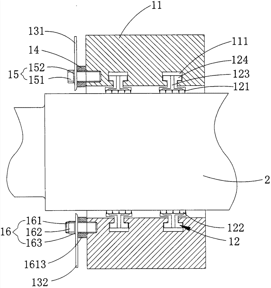
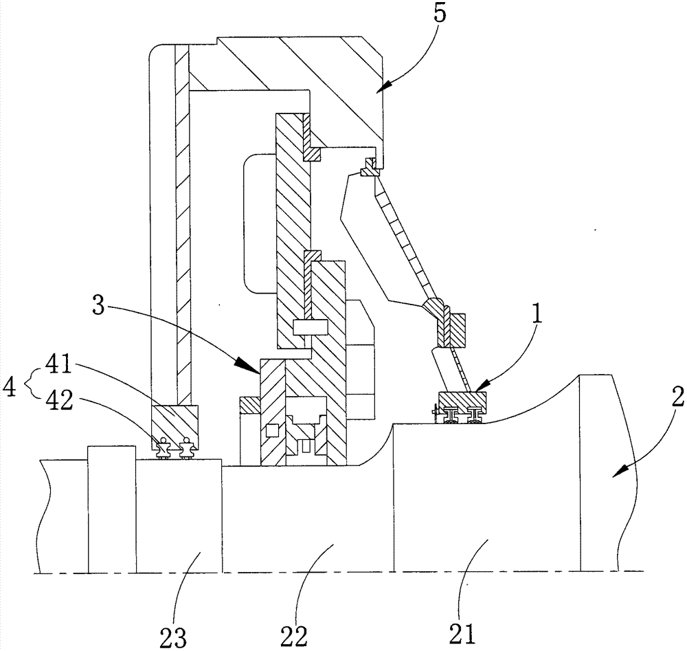
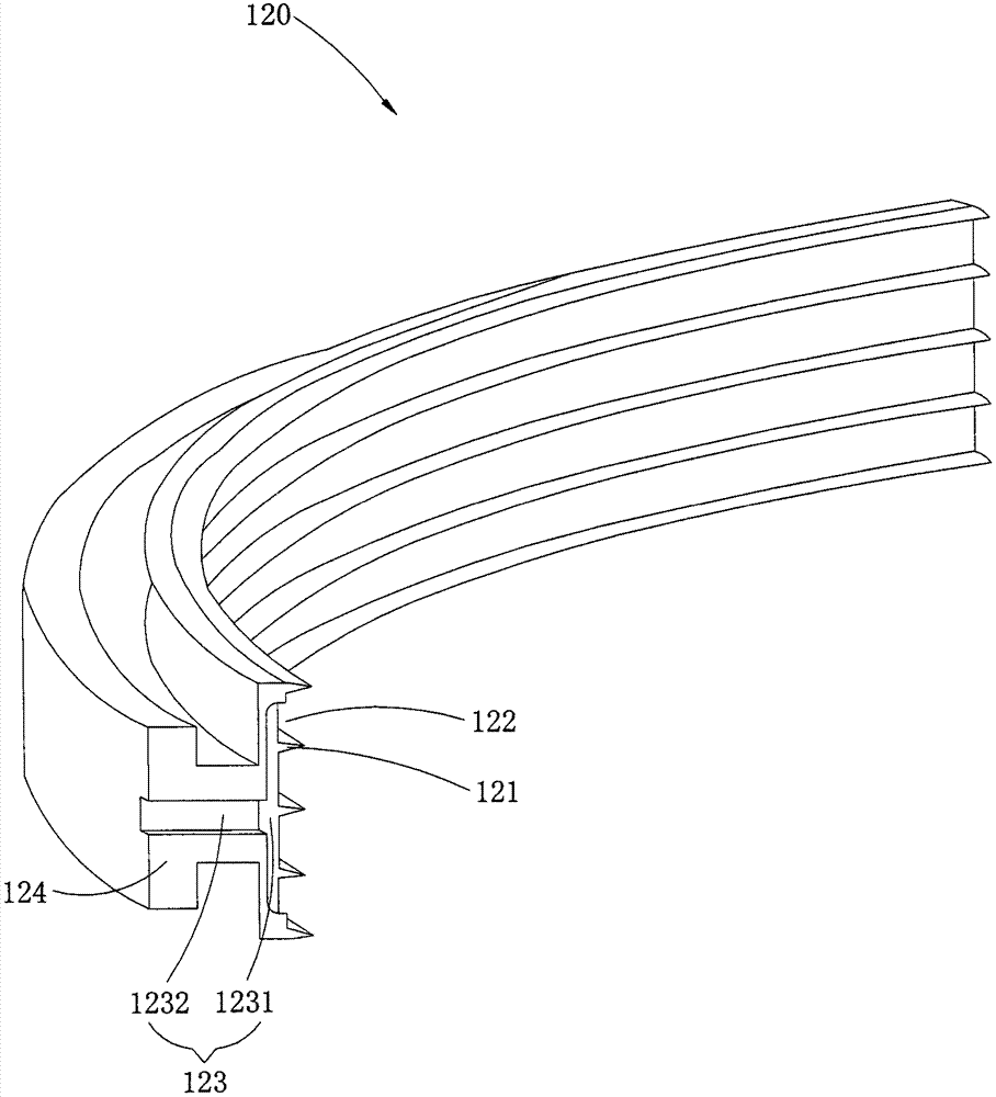
[0039] Such as Figure 1 ~ Figure 3 As shown, the sealing part of the nuclear power plant generator provided by the embodiment of the present invention is used to prevent lubricating oil from sliding along the axial direction of the generator shaft 2, and includes an annular body, which is formed by splicing several sub-arc rings 120. The inner side wall of the arc ring 120 is provided with at least three oil teeth 121 for resisting the sliding of lubricating oil, a slow oil groove 122 interposed between two adjacent oil teeth 121 for buffering part of the lubricating oil and for dredging. The ole...


PUM


Abstract

The invention applies to the technical field of the nuclear power station, and discloses a sealing component of an electric generator at the nuclear power station and a sealing system with the sealing component. The sealing component is used for preventing lubricating oil from sliding along the axial direction of a rotation axis of the electric generator. The sealing component comprises a circular body. The circular body is formed by splicing multiple sub-arc-rings. The inner wall of the sub-arc-ring is alternately provided with at least three oil gears for preventing the lubricating oil from sliding, an oil buffering groove clamped and installed between two adjacent oil gears and used for buffering some lubricating oil and an oil guiding groove for guiding and discharging the lubricating oil in each oil buffering groove. The oil guiding groove is installed on the end face of the sub-arc-ring along the arc length direction of the sub-arc-ring. More than two oil gears and more than one oil buffering groove can be installed on the single sealing component, so that the number of the oil gears and oil buffering grooves on the single sealing component is increased effectively, and the sealing oil-proof effect of the sealing component is improved so as to reduce the amount of the lubricating oil into the electric generator effectively.

Description

technical field [0001] The invention belongs to the technical field of nuclear power plants, and in particular relates to a sealing component of a generator of a nuclear power plant and a sealing system with the sealing component. Background technique [0002] The sealing system of a nuclear power plant generator generally includes a sealing shoe structure for the flow of lubricating oil to isolate the outside air from the hydrogen in the body, and an outer oil retaining structure for preventing the lubricating oil on the end cover from flowing out of the generator and an inner oil retaining structure for preventing lubricating oil on the end cover from entering the generator, the inner oil retaining structure and the outer oil retaining structure are respectively arranged on both sides of the sealing shoe structure. [0003] The seal shoe structure is mainly used for lubricating oil to flow on it, so that on the one hand, it can prevent the hydrogen inside the generator fro...

Claims


Application Information

Patent Timeline
Patent Type & Authority Patents(China)
IPC IPC(8): F16J15/18
CPCF16J15/18
Inventor 贾凯利黎志政何东
Owner CHINA GENERAL NUCLEAR POWER CORP
Why Eureka
Try Eureka