
Integral air energy water heater and draining structure thereof

An air-energy water heater and drainage structure technology, which is applied to fluid heaters, lighting and heating equipment, etc., can solve problems such as unsmooth discharge of condensed water, unsmooth drainage, and poor drainage effect, so as to improve the freezing of drainage and improve The effect of drainage speed and smooth drainage

Active Publication Date: 2015-03-18
GREE ELECTRIC APPLIANCES INC
View PDF11 Cites 9 Cited by
  • Summary
  • Abstract
  • Description
  • Claims
  • Application Information

AI Technical Summary

Problems solved by technology

In the drainage structure of the integrated air energy water heater in the prior art, the condensed water generated by the external machine parts must be discharged through the chassis, the water receiving tray and the drainage joint, and because the area of ​​the water storage tank on the water receiving tray is large, the condensed water will flow The path is long and the drainage is not smooth. In a low temperature environment, it is easy to freeze on the contact surface between the evaporator and the chassis and the corner of the drainage joint, resulting in the inability to discharge the condensed water smoothly, so the drainage effect is poor.

Method used


Image

  • Integral air energy water heater and draining structure thereof
  • Integral air energy water heater and draining structure thereof
  • Integral air energy water heater and draining structure thereof

Examples


Embodiment Construction

[0027] The present invention will be described in detail below with reference to the accompanying drawings and examples. It should be noted that, in the case of no conflict, the following embodiments and features in the embodiments can be combined with each other.

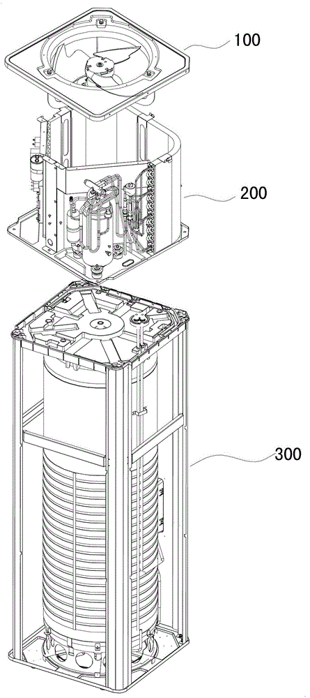
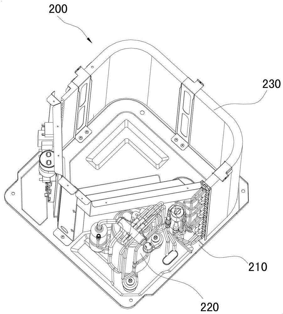
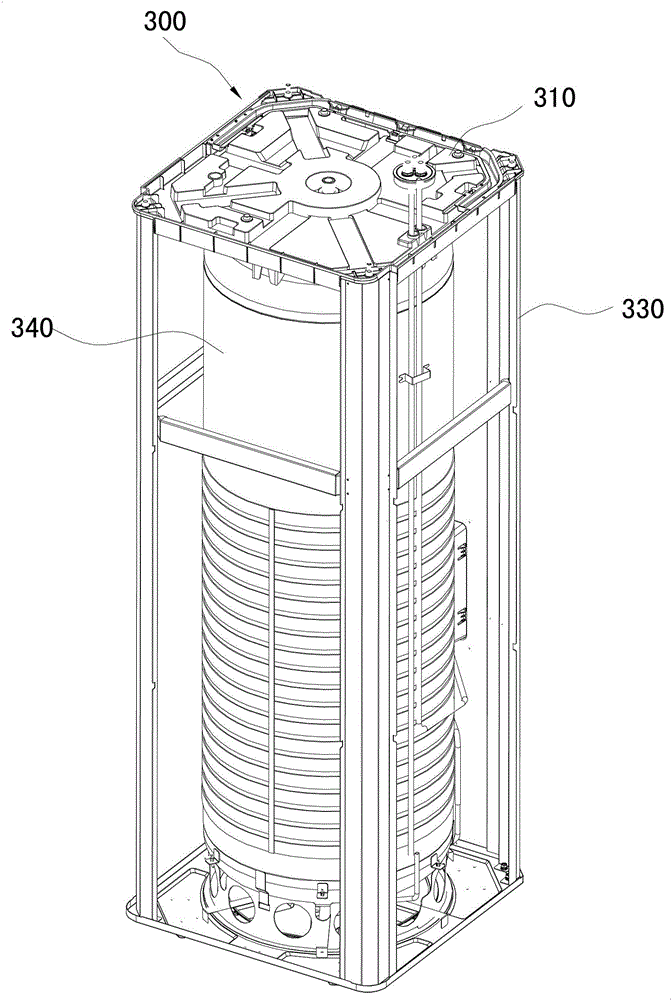
[0028] Such as Figure 1~5 As shown, the drainage structure of the integrated air energy water heater in one embodiment of the present invention includes: a chassis 210, a water receiving tray 310 and a drainage joint 320, the chassis 210 is arranged below the evaporator 230 of the water heater, and The chassis 210 is provided with a first drainage hole 213 and a second drainage hole 212, the second drainage hole 212 is arranged on the chassis 210 below the evaporator 230, and the first drainage hole 213 is arranged at the rest of the chassis 210, preferably Ground, the first drainage hole 213 is arranged on the bottom plate of the groove of the chassis 210 (see Figure 4 ) or other lower positions to quickly dra...


PUM


Abstract

The invention discloses an integral air energy water heater and a draining structure thereof. The draining structure comprises a chassis, a water pan and a draining joint, wherein a first draining hole and a second draining hole are formed in the chassis; the second draining hole is positioned below an evaporator of the water heater; the water pan is arranged below the chassis; a water storage tank is formed in the water pan; a first draining opening is formed in the bottom of the water storage tank and is communicated with a water inlet of the draining joint; a flume is formed in the water pan; an opening of the flume is opposite to the second draining hole; a second draining opening is formed in the bottom of the flume and is communicated with the water inlet of the draining joint. Due to the adoption of the structure, the draining structure disclosed by the invention forms a second-stage draining structure; external rain water of a unit and condensate water left during working of the evaporator are drained by the second-stage draining structure, so that the draining speed of the unit is improved, the draining is smoother, and the condition of icing caused by the drainage of the unit under the low-temperature environment is improved.

Description

technical field [0001] The invention relates to a water storage heater using a heat pump, in particular to an integral air energy water heater and its drainage structure. Background technique [0002] Existing integrated air source water heaters usually consist of an upper external machine part and a lower water tank part, wherein the external machine part includes a chassis, and a compressor and an evaporator installed on the chassis, etc., and the water tank part includes a tank inner body , condensing coil and drip pan. When the air-energy water heater is working, the evaporator will continuously absorb the heat of the air to lower the air temperature, and the moisture in the air will condense on the fins of the evaporator, and the formed water droplets will finally drip onto the chassis, and then flow from the bottom of the chassis. The drain hole discharges into the water storage tank on the water receiving tray, and finally drains into the drain joint from the drain o...

Claims


Application Information

Patent Timeline
Patent Type & Authority Applications(China)
IPC IPC(8): F24H9/16
Inventor 黄俊豪向以华
Owner GREE ELECTRIC APPLIANCES INC
Learn More