
Device and method for automatically setting tool offset value of machine tool

A technology of automatic setting and offset value, applied in the field of CNC lathes, which can solve problems such as the inability to use the interference check program, the difficulty of automating the detection of the tool tip, and the increased workload of the operator.

Active Publication Date: 2015-03-18
NAKAMURATOME SEIMITSU IND
View PDF6 Cites 14 Cited by
  • Summary
  • Abstract
  • Description
  • Claims
  • Application Information

AI Technical Summary

Problems solved by technology

There are many kinds of tools, and there are also many kinds of tool holders used when installing the tools to the tool post. Therefore, it takes a lot of time to manually register the positional relationship to the numerical control device without error.
Moreover, if there is an input error, automatic measurement cannot be performed, or the tool will collide with the tool setting device or other machines, resulting in damage to the equipment
[0008] Therefore, it is difficult to automate the detection of the tool head by the tool setting device. Even for machine tools equipped with an automatic detection unit, it is mostly done manually. get bigger
[0009] Also, when using the interference check program to check the tool for interference, it is necessary to register the shape data of the tool mounted on the tool holder and the tool holder to the PC in advance.
In a lathe equipped with an automatic tool changer and multiple turrets, since a large number of tools are used, it is very troublesome to register the shape data of these tools
In addition, if there is an input error, it will cause interference even if it is detected, or a warning of interference will be issued even if it does not actually cause interference
Therefore, there are cases where it is almost impossible to use even if the interference check program is prepared

Method used


Image

  • Device and method for automatically setting tool offset value of machine tool
  • Device and method for automatically setting tool offset value of machine tool
  • Device and method for automatically setting tool offset value of machine tool

Examples


Embodiment Construction

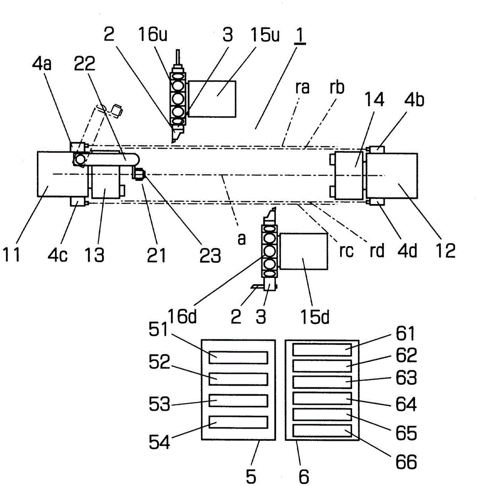
[0046]Hereinafter, an embodiment of the present invention will be described by taking, as an example, a dual-spindle opposed CNC lathe provided with two turret tool holders. A numerically controlled lathe includes an equipment main body 1 , a numerically controlled device 5 and a PC (computer) 6 . The main body 1 of the equipment includes a left spindle and a right spindle facing each other on the same spindle axis a. The left spindle is pivotally supported by a left headstock 11 fixed on the bed, and a left chuck 13 is attached to the right end thereof. The right main shaft is pivotally supported by a right main headstock 12 which is movable and positionable in a direction parallel to the main shaft axis a (Z-axis direction), and a right chuck 14 is mounted on the left end thereof.

[0047] When viewed from the operator's direction, the upper tool rest 15u and the lower tool rest 15d are disposed above the rear side and below the near side with the spindle axis a interposed t...


PUM


Abstract

Provided are a method and device for automatically setting a relative position relation between a tool post of a numerical control (NC) machine tool and an edge of a tool mounted on the tool post and fully automating work of setting a tool offset value of a machine tool in which multiple tools are used. Tools mounted on tool posts are measured by cameras or laser length measuring devices. A temporary tool offset value is set using shape data of the tool and data indicating a direction of an edge of the tool designated to a machining program and / or tool data registered with a controller. The edge of the tool is automatically brought into contact with a tool setter using the temporary tool offset value. Thereby, the accurate tool offset value is acquired and set for an NC device. It is possible to simulate a machining operation using the temporary tool offset value or to check interference using the shape data of the tool which is acquired by the camera or the laser length measuring devices.

Description

technical field [0001] The present invention relates to a method and an apparatus for automatically setting a relative positional relationship between a tool post of an NC (numerically controlled) machine tool and a head of a tool mounted on the tool post. The present invention relates to the above-mentioned method and device suitable for a CNC (numerical control) lathe equipped with a plurality of turret tool holders and an automatic tool changer. Background technique [0002] The CNC machine tool processes the workpiece by controlling the position of the tool holder according to the instructions of the processing program. However, since the cutter head of the tool mounted on the tool holder actually processes the workpiece, if the relative positional relationship between the position of the tool holder and the cutter head is not known, the workpiece cannot be processed into a correct shape. [0003] Therefore, after the tool is mounted on the tool post, for each tool moun...

Claims


Application Information

Patent Timeline
IPC IPC(8): G05B19/404
CPCG05B19/401G05B19/404G05B19/4015G05B2219/37025G05B2219/37559G05B2219/50026G05B2219/50135G05B2219/50291
Inventor 本间秀树
Owner NAKAMURATOME SEIMITSU IND
Learn More