
Low complexity soft output MIMO decoder

A technology of soft bits and receivers, applied in transmission systems, digital transmission systems, radio transmission systems, etc., can solve problems such as poor performance, decoding algorithms increase the cost of MIMO systems, and low complexity

Active Publication Date: 2015-03-18
NORDIC SEMICONDUCTOR
View PDF4 Cites 4 Cited by
  • Summary
  • Abstract
  • Description
  • Claims
  • Application Information

AI Technical Summary

Problems solved by technology

The complexity of the decoding algorithm and the amount of hardware used (due to the multiple antennas) increases the cost of implementing a MIMO system
Existing techniques such as ML techniques provide technical solutions for decoding symbol sets with high performance (e.g. low bit rate (BER)), but require a lot of computation
Other techniques such as zero-forcing (ZF) techniques have lower complexity than ML techniques but have poorer performance (e.g. high BER)

Method used


Image

  • Low complexity soft output MIMO decoder
  • Low complexity soft output MIMO decoder
  • Low complexity soft output MIMO decoder

Examples


Embodiment Construction

[0021] The present disclosure is best understood by reference to the detailed drawings and following description. Various embodiments are discussed below with reference to the figures. Those skilled in the art will readily appreciate, however, that the detailed description given herein with reference to the figures is for explanatory purposes only, as the methods and systems may extend beyond the described embodiments. Given the teachings and requirements of a particular application may, for example, yield numerous alternative and suitable ways of carrying out the functionality of any detail described herein. Thus, any method can be extended beyond specific implementation options in the embodiments described and shown below.

[0022] References to "one embodiment," "at least one embodiment," "an embodiment," "an example," "example," "for example," etc. indicate that the embodiment or example so described may include particular features, structure, characteristic, property, e...


PUM


Abstract

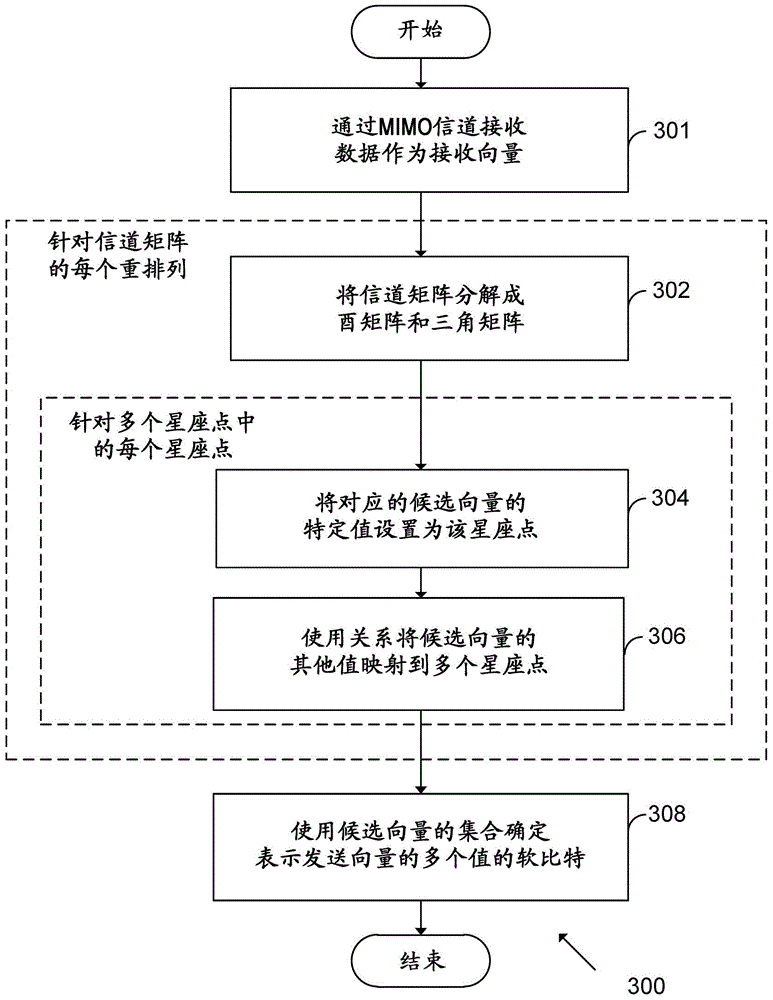
A method and processing block for receiving data transmitted in a MIMO system is provided. Data is transmitted as a transmit vector of values from multiple transmitting antennas and received as a receive vector of values at multiple receiving antennas. Candidate vectors are determined based on each of a plurality of constellation points of the constellation configuration used in the transmission scheme. A channel matrix is decomposed into a unitary matrix and a triangular matrix, such that a relationship links: (i) a function of the unitary matrix and the receive vector, and (ii) a multiplication of the triangular matrix and the transmit vector. A best candidate vector from the set of candidate vectors is utilized for the computation of soft bits representing the values of the transmit vector.

Description

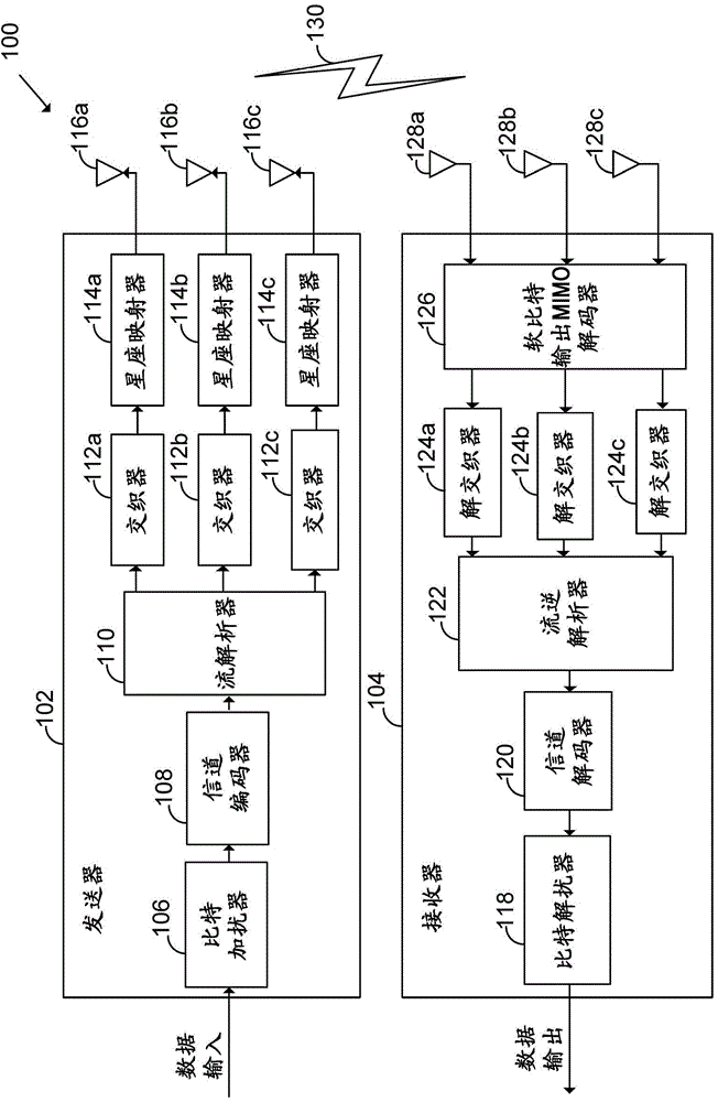
Background technique [0001] Multiple-Input Multiple-Output (MIMO) systems are increasingly used in communication systems. A MIMO system includes multiple transmit antennas and multiple receive antennas to facilitate increased data rates compared to single-input single-output systems. [0002] figure 1 is a block diagram illustrating the MIMO system 100 . MIMO system 100 includes transmitter 102 and receiver 104 . The transmitter 102 includes a number of modules including a bit scrambler 106, a channel encoder 108, a stream parser 110, and may include a number of interleavers 112a, 112b, and 112c (which will be referred to hereinafter as 112), a plurality of constellation mappers 114a, 114b and 114c (which will be referred to hereinafter as 114), and a plurality of transmit antennas 116a, 116b and 116c (which will be referred to as 116 hereinafter). A plurality of first RF units (not shown) may be present between the plurality of constellation mappers 114 and corresponding ...

Claims


Application Information

Patent Timeline
IPC IPC(8): H04L25/03H04L25/02H04L27/38H04L69/14
CPCH04B7/0882H04L25/0246H04L25/02H04L25/03318H04B7/046H04B7/024H04L25/0204H04B7/0456
Inventor S·坎基帕蒂S·夏尔马U·维伦基
Owner NORDIC SEMICONDUCTOR
Learn More