Regenerating method of catalytic conversion catalyst

A catalytic conversion and catalyst technology, applied in the direction of catalyst regeneration/reactivation, physical/chemical process catalyst, metal/metal oxide/metal hydroxide catalyst, etc., can solve the problem of poor performance of catalyst flow rate modulation, high frequency of catalyst regeneration, etc. problem, achieve the effect of reducing the frequency of charcoal regeneration and avoiding the loss of surface area

Active Publication Date: 2015-03-25
ZHEJIANG UNIV
View PDF10 Cites 4 Cited by
  • Summary
  • Abstract
  • Description
  • Claims
  • Application Information

AI Technical Summary

Problems solved by technology

[0011] The purpose of the present invention is to provide a catalytic conversion catalyst regeneration method for the problems of high catalyst regeneration frequenc

Method used


Image

  • Regenerating method of catalytic conversion catalyst
  • Regenerating method of catalytic conversion catalyst

Examples


Example Embodiment

[0027] Example 1

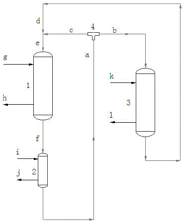
[0028] The catalyst f removed from the reactor 1 first enters the first regenerator 2 and is purged and regenerated by the first regeneration gas i at 170°C. The residence time τ of the catalyst in the first regenerator 2 2 Is the residence time τ of the catalyst in reactor 1 1 10 times. The primary regenerator a at the outlet of the first regenerator 2 is delivered to the catalyst flow distributor 4 and then divided into two streams b and c, respectively, enter the second regenerator 3 and the reactor 1, and enter the primary regenerator flow of the reactor 1. The flow rate of stream c accounts for 1% of the total flow rate of the primary regenerant in stream a. The primary regenerant in stream b enters the second regenerator 3 through the second regeneration gas k to obtain the secondary regeneration. The regenerant d and the primary regenerant stream c enter the reactor 1 together after being combined.

[0029] The form of the reactor 1, the first regenerator...

Example Embodiment

[0035] Example 2

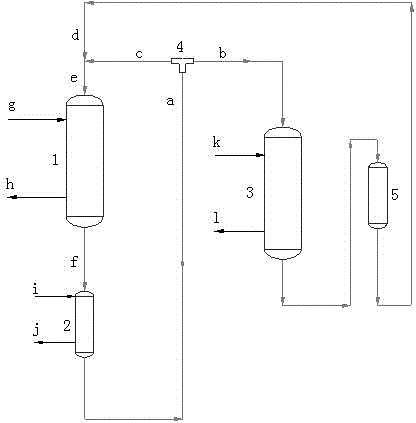
[0036] The catalyst f removed from the reactor 1 first enters the first regenerator 2 and is purged and regenerated by the first regeneration gas i at 650°C. The residence time τ of the catalyst in the first regenerator 2 2 Is the residence time τ of the catalyst in reactor 1 1 5 times. The primary regenerator a at the outlet of the first regenerator 2 is delivered to the catalyst flow distributor 4 and then divided into two streams b and c, respectively, enter the second regenerator 3 and the reactor 1, and enter the primary regenerator flow of the reactor 1. The flow rate of stream c accounts for 60% of the total flow rate of the primary regenerant in stream a. The primary regenerant in stream b enters the second regenerator 3 through the second regeneration gas k for secondary regeneration. The regenerant d and the primary regenerant stream c enter the reactor 1 together after being combined.

[0037] The form of the reactor 1, the first regenerator 2 and the...

Example Embodiment

[0043] Example 3

[0044] The catalyst f removed from the reactor 1 first enters the first regenerator 2 and is purged and regenerated by the first regeneration gas i at 300°C. The residence time τ of the catalyst in the first regenerator 2 2 Is the residence time τ of the catalyst in reactor 1 1 0.1 times. The primary regenerator a at the outlet of the first regenerator 2 is delivered to the catalyst flow distributor 4 and then divided into two streams b and c, respectively, enter the second regenerator 3 and the reactor 1, and enter the primary regenerator flow of the reactor 1. The flow rate of stream c accounts for 100% of the total flow rate of the primary regenerant in stream a. The primary regenerant in stream b enters the second regenerator 3 through the second regeneration gas k for secondary regeneration. The regenerant d and the primary regenerant stream c enter the reactor 1 together after being combined.

[0045] The form of the reactor 1, the first regenerator 2 and ...


PUM


Abstract

The invention discloses a regenerating method of a catalytic conversion catalyst. The regenerating method comprises the following steps: a catalyst which is transferred from a reactor firstly enters a first generator to be blown and regenerated by first regenerated gas; and a primary regenerant at the outlet of the first generator is conveyed to a catalyst flow distributor and is divided into two material flows which respectively enters a second regenerator and the reactor, wherein the flow of the primary regenerant flow entering the reactor accounts for 1-100% of the total flow of the primary regenerant in the flow and a part of primary regenerant enters a second regenerator to be secondarily regenerated by virtue of second regenerated gas to obtain a secondary regenerant which is combined with the primary regenerant flow and enters the reactor together. According to the regeneration method disclosed by the invention, the capacity of the existing reactor can be effectively improved, frequent charking regeneration of the catalyst is avoided and the regenerating temperature and temperature rise are reduced, and the total service life of the catalyst is prolonged. Moreover, the flow rate of the catalyst in different mobile bed reactors is independently regulated, and the regenerating method can be used in industrial production of methanol to propylene.

Description

technical field [0001] The invention relates to a regeneration method of a catalytic conversion catalyst, which is particularly suitable for the regeneration of a moving-bed methanol-to-propylene catalyst. Background technique [0002] In many catalytic conversion processes of hydrocarbons, the main reactions are methylation reaction, dehydrogenation, cyclodehydrogenation, isomerization, cracking reaction and carbon deposition reaction, among which the carbon deposition reaction will lead to the reversibility of the catalyst. Deactivation, this reversible deactivation mainly comes from the carbon deposition species produced during the reaction covering the active center of the catalyst or blocking the internal / external pores of the catalyst. [0003] The formation mechanism of coke species is very complicated, and the formation mechanism is different for different catalysts. Generally speaking, it can be considered that the high-carbon products generated after oligomerizatio...

Claims


Application Information

Patent Timeline
IPC IPC(8): B01J38/22B01J38/52B01J38/58B01J38/04B01J38/06B01J29/90B01J23/96
Inventor 蒋斌波蒋云涛周冰洁阳永荣王靖岱廖祖维黄正梁
Owner ZHEJIANG UNIV
Why Eureka
Try Eureka