Condenser for biological pharmacy

A technology for biopharmaceuticals and condensers, which is applied in centrifuges and other directions to improve cooling efficiency and service life.

Inactive Publication Date: 2015-03-25
CHENGDU OLYMVAX BIOPHARM
View PDF5 Cites 3 Cited by
  • Summary
  • Abstract
  • Description
  • Claims
  • Application Information

AI Technical Summary

Problems solved by technology

[0004] The technical problem to be solved by the present invention is to provide a condenser for biopharmaceuticals, which overcomes the problem that the existing condensing structure cannot be applied to both closed cooling devices and semi-open cooling devices
The present invention overcomes the problem that the existing condensation structure cannot be applied to both closed cooling devices and semi-open cooling devices by setting a connecting pipe between condensation column III and condensation column IV

Method used


Image

  • Condenser for biological pharmacy
  • Condenser for biological pharmacy

Examples


Embodiment 1

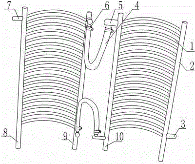
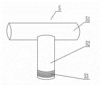
[0021] Such as figure 1 , figure 2 As shown, a condenser for biopharmaceuticals includes condensation column I2, condensation column II8, condensation column III9, condensation column IV10, and several semicircular condensation tubes 1 are arranged between condensation column II8 and condensation column III9. Between the condensation column I2 and the condensation column IV10, there are several semicircular condensation pipes 1. The condensation pipes 1 are made of copper. Both the condensation column III9 and the condensation column IV10 are provided with joints 5. The joints 5 include horizontal shafts 51, A vertical rod 52 perpendicular to the horizontal axis 51, a threaded surface 53 is provided on the outer wall of one end of the vertical rod 52 connected to the connecting pipe 5, and a connecting pipe 4 is provided between the joint 5 on the condensation column III9 and the joint 5 on the condensation column IV10 , the connecting pipe 4 is a PVC hose, the connection be...

Embodiment 2

[0023] Such as figure 1 , figure 2 As shown, a condenser for biopharmaceuticals includes condensation column I2, condensation column II8, condensation column III9, condensation column IV10, and several semicircular condensation tubes 1 are arranged between condensation column II8 and condensation column III9. Between the condensation column I2 and the condensation column IV10, there are several semicircular condensation pipes 1. The condensation pipes 1 are made of copper. Both the condensation column III9 and the condensation column IV10 are provided with joints 5. The joints 5 include horizontal shafts 51, A vertical rod 52 perpendicular to the horizontal axis 51, a threaded surface 53 is provided on the outer wall of one end of the vertical rod 52 connected to the connecting pipe 5, and a connecting pipe 4 is provided between the joint 5 on the condensation column III9 and the joint 5 on the condensation column IV10 , the connecting pipe 4 is a corrugated pipe made of sta...


PUM


Abstract

The invention relates to a condenser for biological pharmacy. The condenser for biological pharmacy comprises a condensation column I, a condensation column II, a condensation column III and a condensation column IV. A plurality of condensation pipes shaped like semi-circles in a sunken mode are arranged between the condensation column II and the condensation column III, and a plurality of condensation pipes shaped like semi-circles in a sunken mode are arranged between the condensation column I and the condensation column IV. The condensation column III and the condensation column IV are both provided with connectors, a connection pipe is arranged between the connector on the condensation column III and the connector on the condensation column IV, fixing devices are arranged on junctions of the connection pipe and the connectors, a water inlet pipe connector is arranged at the lower end of the condensation column I, and a water outlet pipe connector is arranged at the upper end of the condensation column II. According to the condenser for biological pharmacy, as the connection pipe is arranged between the condensation column III and the condensation column IV, the defect that an existing condensation structure can not be applied to a closed cooling type and also applied to a semi-open type cooling device is overcome.

Description

technical field [0001] The invention relates to the field of pharmaceutical auxiliary equipment, in particular to a condenser for biopharmaceuticals. Background technique [0002] In the biopharmaceutical industry, the centrifuge is often an indispensable auxiliary mechanical tool for the pharmaceutical process. It is often used for the precipitation and separation of solutions. The centrifuge is a kind of test equipment for separating solids and liquids through centrifugal force. The materials in the centrifuge are under centrifugal force. Under the effect of the action of layering, the heavy solid is thrown on the inner wall of the drum, and the light liquid is in the center of the drum and flows to the upper part of the drum to be collected by the liquid collection plate. The drum will generate a lot of heat during operation, and it needs to be cooled by a cooling device, which includes a condensing structure and a fixing device for fixing the condensing structure. High-...

Claims


Application Information

Patent Timeline
Patent Type & Authority Applications(China)
IPC IPC(8): B04B15/02
Inventor 赵丹王泽举
Owner CHENGDU OLYMVAX BIOPHARM
Why Eureka
Try Eureka