Vacuum clamping device for numerical-control milling

A technology of clamping device and vacuum generating device, which is applied in the direction of positioning device, metal processing equipment, metal processing machinery parts, etc., can solve the problems of poor versatility and easy deformation, and achieve strong versatility, high efficiency and fast The effect of installation

Inactive Publication Date: 2015-03-25
SEKSUN TECH SUZHOU
View PDF6 Cites 11 Cited by
  • Summary
  • Abstract
  • Description
  • Claims
  • Application Information

AI Technical Summary

Problems solved by technology

[0003] Its disadvantages are: electromagnetic table adsorption or clamping with T-shaped slot table has its limitations. Electromagnetic table adsorption can only absorb steel workpieces, and T-shaped slot table

Method used


Image

  • Vacuum clamping device for numerical-control milling
  • Vacuum clamping device for numerical-control milling
  • Vacuum clamping device for numerical-control milling

Examples


Embodiment Construction

[0013] The preferred embodiments of the present invention will be described in detail below in conjunction with the accompanying drawings, so that the advantages and features of the present invention can be more easily understood by those skilled in the art, so as to define the protection scope of the present invention more clearly.

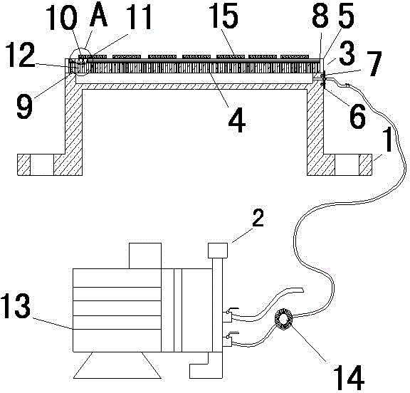
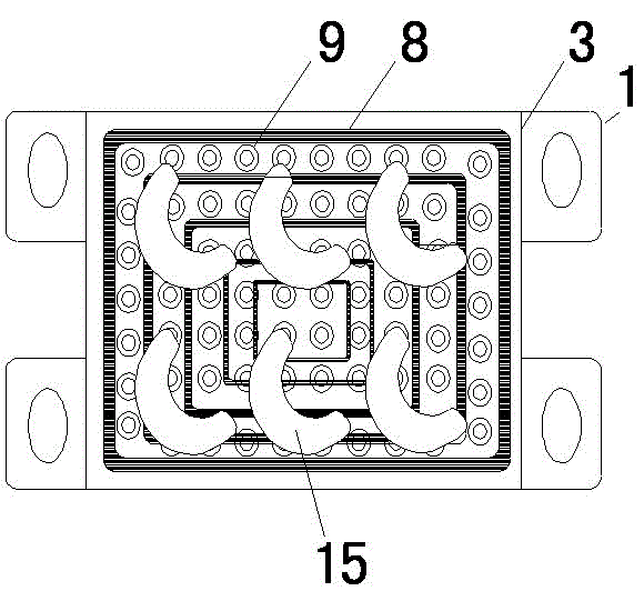
[0014] Such as figure 1 The embodiment of the present invention shown in -2: a vacuum clamping device for CNC milling, including a tooling seat 1, a vacuum generating device 2 and a tooling table 3; the tooling seat 1 is designed with an air guide groove 4 and The sealing groove 5, the inlet end of the air guiding groove 4 is connected with the tooling table 3, and the outlet end of the air guiding groove 4 has a sealing cover 6 locked together with the bottom end surface of the tooling seat 1 by screws; the vacuum generating device 2 and The outlet of the air guide groove 4 is connected; the seal groove 5 is provided with a sealing ring 8, and t...


PUM


Abstract

The invention discloses a vacuum clamping device for numerical-control milling. The vacuum clamping device comprises a tool base and a vacuum generating device. An air guide groove and a sealing groove are formed in the tool base. An air inlet of the air guide groove is connected with a tool table. An outlet of the air guide groove is provided with a sealing cover which is connected with the bottom end face of the tool base through a screw. The vacuum generating device is connected with the tool base at the outlet of the air guide groove. A sealing ring is arranged in the sealing groove and connected with one end face of the tool table. The tool table is provided with a plurality of suction nozzles which can adsorb a plurality of work-pieces. In the working process, the vacuum clamping device is installed on a working table of a numerical-control milling machine, the vacuum generating device is started, the work-pieces are placed on the tool table, and milling can be started till to completion. The vacuum clamping device for numerical-control milling is high in universality without special location, particularly suitable for the various special-shaped thin-wall light work-pieces, capable of milling a plurality of identical work-pieces, and high in efficiency.

Description

technical field [0001] The invention relates to a vacuum clamping device for numerical control milling. Background technique [0002] The clamping device used for CNC lathe processing in the prior art is mostly adsorbed by an electromagnetic table or clamped by a T-shaped slot table. [0003] Its disadvantages are: electromagnetic table adsorption or clamping with T-shaped slot table has its limitations. Electromagnetic table adsorption can only absorb steel workpieces, and T-shaped slot table clamping is suitable for thin-walled, light-weight or special-shaped parts. It cannot be clamped or easily deformed, or there are many places that cannot be processed by milling, and the versatility is not strong. . Contents of the invention [0004] The technical problem mainly solved by the present invention is to provide a vacuum clamping device for numerical control milling, which is convenient for clamping, has strong versatility, does not easily deform parts, and has high pre...

Claims


Application Information

Patent Timeline
IPC IPC(8): B23Q3/08
CPCB23Q3/088
Inventor 顾英杰汪洋王龙军
Owner SEKSUN TECH SUZHOU
Why Eureka
Try Eureka