Automobile light self-adaptation control device based on CAN (controller area network) bus and control method thereof

A CAN bus, adaptive control technology, applied in signal devices, optical signals, vehicle components, etc., can solve the problems of drivers not being able to see the nearby road, threats to the driver's personal safety, and traffic safety accidents, etc., to reduce Illumination of blind spots, elimination of potential safety hazards, and reduction of misoperation

Inactive Publication Date: 2015-03-25
CHANGAN UNIV
View PDF6 Cites 5 Cited by
  • Summary
  • Abstract
  • Description
  • Claims
  • Application Information

AI Technical Summary

Problems solved by technology

In order to reduce the driver's driving fatigue, an automatic adjustment device for high and low beams has emerged as the times require. However, the current automatic adjustment device for high and low beams only operates when automobiles meet, and most of them use photosensitive materials to detect light intensity, such as photoresistors, photosensitive Diodes, etc., which are greatly affected by temperature, slow in response, and poor in physical properties
When the car is turning at night, the car lights move from the middle of the road to the side of the road. If the lights are not switched to the low beam at this time, the driver will not be able to see the nearby road clearly, which will easily lead to misjudgment
If the car does not switch the headlights to low beams in time when the car is driving straight from high speed to entering the ramp or turning on urban roads and winding roads, traffic safety accidents are very likely to occur, posing a certain threat to the driver's personal safety

Method used


Image

  • Automobile light self-adaptation control device based on CAN (controller area network) bus and control method thereof
  • Automobile light self-adaptation control device based on CAN (controller area network) bus and control method thereof

Examples


Embodiment Construction

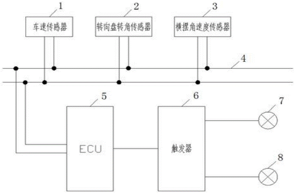
[0025] The present invention will be described in further detail below in conjunction with the accompanying drawings. see figure 1 , the present invention includes a speed sensor 1 for monitoring the vehicle speed, a steering wheel angle sensor 2 for monitoring the steering wheel angle, a yaw rate sensor 3 for monitoring the yaw angle of the vehicle, and a sensor data set for collecting The driving computer (ECU) 5; the speed sensor 1, the steering wheel angle sensor 2 and the yaw rate sensor 3 are respectively connected to the signal input terminal of the driving computer 4 through the CAN bus 4; the signal output terminal of the driving computer 4 is connected through the trigger 6 They are connected with the low beam light 7 and the high beam light 8 respectively.

[0026] The speed sensor 1 is connected with the speedometer of the car. The steering wheel angle sensor 2 is arranged on the steering wheel shaft of the automobile, and the yaw rate sensor 3 is arranged under ...


PUM


Abstract

The invention belongs to the technical field of automobile electronic devices, and particularly relates to an automobile distance light and passing light self-adaptation control device based on a CAN (controller area network) bus and used when an automobile turns, and a control method of the device. The device comprises a vehicle speed sensor, a steering wheel angle sensor, a yam velocity sensor and an ECU (electronic control unit) used for collecting and processing data of the vehicle speed sensor, the steering wheel angle sensor and the yam velocity sensor, wherein the vehicle speed sensor, the steering wheel angle sensor and the yam velocity sensor are all connected with a signal input end of the ECU through the CAN bus, and an output end of the ECU is connected with a low beam and a high beam through a trigger respectively. According to the method, the collected data of the sensors are compared with preset threshold values, whether the automobile enters a curve or goes off the curve is judged, the light beam and the high beam are automatically switched when the automobile turns, dead angles of lighting are reduced, and safety hidden risks are eliminated. Therefore, misjudgment operations of a driver are prevented, and the operation burden of the driver is reduced.

Description

technical field [0001] The invention belongs to the technical field of automotive electronic devices, and in particular relates to a CAN bus-based adaptive control device for far and near lights when turning a car and a control method thereof. Background technique [0002] At present, with the continuous improvement of the economy, the number of cars in my country is increasing year by year, and more serious driving safety problems follow. When driving at night, the driver usually turns on the high beams to increase his field of vision, but when two vehicles meet or overtake, the headlights of the car should be switched to low beams, which greatly increases the driver's driving fatigue . In order to reduce the driver's driving fatigue, an automatic adjustment device for high and low beams came into being. However, at present, the automatic adjustment device for high and low beams only operates when automobiles meet, and most of them use photosensitive materials to detect li...

Claims


Application Information

Patent Timeline
Patent Type & Authority Applications(China)
IPC IPC(8): B60Q1/14
Inventor 白艳付锐许渝峰任肖齐超飞
Owner CHANGAN UNIV
Why Eureka
Try Eureka