Brake lamp control unit

A technology for control devices and brake lights, which is applied in signal devices, transportation and packaging, optical signals, etc., can solve the problems of short life, low judgment accuracy, complex structure, etc. Effect

Inactive Publication Date: 2015-03-25
上海盈智汽车电子有限公司
View PDF0 Cites 1 Cited by
  • Summary
  • Abstract
  • Description
  • Claims
  • Application Information

AI Technical Summary

Problems solved by technology

[0004] Based on this, it is necessary to provide a brake light for the problems of low accuracy in judging the braking action of the general automobile brake light, easy failure of contacts due to poor contact caused by ablation, short life, complex structure and difficult manufacture. Brake light control device with high accuracy of action judgment, no mechanical contact, long life, simple structure and easy manufacture

Method used


Image

  • Brake lamp control unit
  • Brake lamp control unit

Examples


Embodiment Construction

[0016] The present invention will be described in detail below with reference to the drawings and specific embodiments.

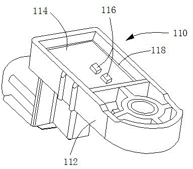
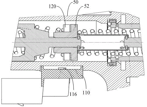
[0017] Such as figure 1 with figure 2 As shown, in one embodiment, a brake light control device includes a body 110 and a magnetic ring 120. The magnetic ring 120 is used to sleeve the inner piston 52 of the brake pump 50. The magnetic ring 120 has two poles, which are respectively distributed on two surfaces of the magnetic ring 120. The body 110 includes a base 112, a circuit board 114 and a Hall sensor 116. The base 112 is made of plastic. The circuit board 114 is installed in the base 112, and the circuit board 114 is integrated with a control circuit for controlling to turn on or off the brake light. A potting glue 118 is sealed between the outer circumference of the circuit board 114 and the base 112. The Hall sensor 116 is integrated on the circuit board 114 and is electrically connected to the control circuit. Generally, the Hall sensor 116 is a un...


PUM


Abstract

A brake lamp control unit comprises a body and a magnet ring; the magnet ring is used for sleeving an inner piston of a brake pump. The body comprises a base, a circuit board and a Hall sensor; the circuit board is integrated to a control circuit; the control circuit is used for controlling on or off of a brake lamp; the Hall sensor is integrated to the circuit board and electrically connected with the control circuit; the body is installed to an outer wall of the brake pump in a plane where the magnet ring locates when the Hall sensor deviates from an initial position of the inner piston. When braking starts and a brake pedal drives the inner piston to move so that the magnet ring arrives or exceeds the Hall sensor, the Hall sensor outputs a first level signal, and the control circuit controls on of the brake lamp; when braking stops and the inner piston drives the magnet ring to pass by the Hall sensor and return to the initial position, the Hall sensor outputs a second level signal, and the control circuit controls off of the brake lamp. The brake lamp control unit is capable of accurately judging a braking action, the failure caused by poor contact is avoided, and the service life is longer.

Description

Technical field [0001] The invention relates to the field of automobile lamp control, in particular to a brake lamp control device. Background technique [0002] Brake lights are mounted on both sides of the rear of a car to warn vehicles behind to avoid rear-end collisions. Normally, the brake light is controlled by the automobile brake light switch. The general automobile brake light switch is a mechanical structure, which is mainly composed of a drive push rod, a return spring, an electric contact shrapnel and a contact. The driving push rod conducts the braking action of the brake pedal, which directly or indirectly realizes the opening and closing of the contacts. The brake light switch is installed on the brake pedal bracket. When the brake pedal is stepped on, the switch is turned on. The ECU (Electronic Control Unit) obtains the brake signal and controls to light the brake light. At the same time, the torque converter locks The stop clutch is disengaged to prevent the e...

Claims


Application Information

Patent Timeline
Patent Type & Authority Applications(China)
IPC IPC(8): B60Q1/44
Inventor 曾涛丁贵亮刘伟罗德生徐军舒展
Owner 上海盈智汽车电子有限公司
Why Eureka
Try Eureka