Motor-integrated electric control brake master cylinder driving system

An electronically controlled braking and motor-integrated technology, applied in brake transmissions, brakes, vehicle components, etc., can solve problems such as poor pedal feel, poor active safety function, and large booster volume, to ensure safe and reliable operation, universal Strong performance and good pedal feel

Active Publication Date: 2015-03-25
JILIN UNIV
View PDF8 Cites 15 Cited by
  • Summary
  • Abstract
  • Description
  • Claims
  • Application Information

AI Technical Summary

Problems solved by technology

[0005] The technical problem to be solved by the present invention is to overcome the existing problems in the existing hydraulic braking system, such as large booster volume, poor active safety function and poor pedal feeling when braking, and provide an integrated motor electric control brake system. Master cylinder drive system

Method used


Image

  • Motor-integrated electric control brake master cylinder driving system
  • Motor-integrated electric control brake master cylinder driving system
  • Motor-integrated electric control brake master cylinder driving system

Examples


Embodiment Construction

[0035] The present invention is described in detail below in conjunction with accompanying drawing:

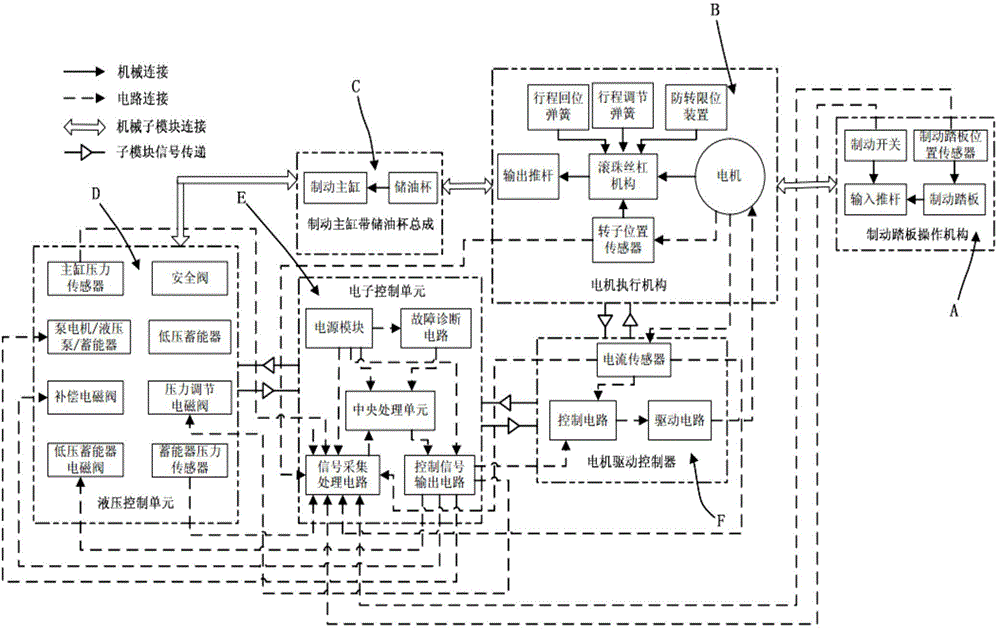
[0036] refer to figure 1 , the integrated motor electronic control brake master cylinder drive system of the present invention includes a brake pedal operating mechanism A, a motor actuator B, a brake master cylinder assembly C, a hydraulic control unit D, an electronic control unit E and a motor drive controller F.

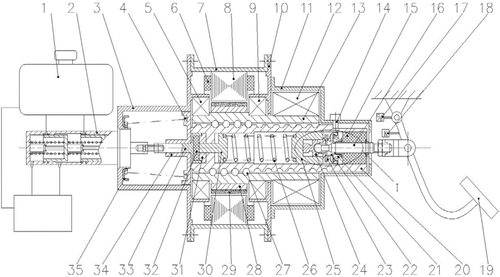
[0037] The brake pedal operating mechanism A is mainly composed of an input push rod 16 , a brake pedal position sensor 17 , a brake switch 18 and a brake pedal 19 .

[0038] The upper end of the brake pedal 19 has a section of groove and the right end of the input push rod 16 is connected by bolts, and the brake pedal angular position sensor 17 is connected with the topmost rotating shaft of the brake pedal 19 by bolts, so that the rotating part of the brake pedal angular position sensor 17 Rotate together with the brake pedal shaft; brake switch 18 is in cont...


PUM


Abstract

The invention discloses a motor-integrated electric control brake master cylinder driving system and aims at solving the problem that an existing hydraulic brake system is large in power-assisted volume and poor in active safety function and pedaling feeling during braking. The motor-integrated electric control brake master cylinder driving system comprises a brake pedal operating mechanism, a motor executing mechanism and a hydraulic control unit. The motor executing mechanism comprises a lead screw threaded rod mechanism, a stroke return mechanism, an input sealing mechanism, a housing mechanism, a lead screw threaded rod driving mechanism and a rotor position sensor. The stroke return mechanism is installed in a front end cover, the lead screw threaded rod mechanism is installed on the front end cover and a middle end cover through bearings and located in a rear end cover, the right end face of a stroke return spring rear seat of the stroke return mechanism is in contact with the left end face of a lead screw threaded rod in the lead screw threaded rod mechanism, a third-section shaft of a lead screw nut in the lead screw threaded rod mechanism is sleeved with the lead screw threaded rod driving mechanism, a first-section shaft of the lead screw nut is sleeved with the rotor position sensor, and the input sealing mechanism is installed in a first stepped blind hole of the lead screw threaded rod.

Description

technical field [0001] The invention relates to an integrated motor electric control brake master cylinder drive system in the technical field of automobile chassis. Background technique [0002] Since the birth of the automobile, the vehicle braking system has played a vital role in the safety of the vehicle. Modern automobiles generally adopt hydraulic braking system, which consists of brake pedal, brake master cylinder, vacuum booster, hydraulic pipeline, brake, etc. When braking, the driver depresses the brake pedal to push the brake master cylinder to move. The brake master cylinder converts the mechanical energy of the braking force input by the pedal into hydraulic energy, and the high-pressure brake fluid reaches the brake wheel cylinder through the hydraulic pipeline to achieve braking. However, the above-mentioned hydraulic braking system has certain shortcomings: the burden on the driver is relatively large; after integrating vacuum booster and active safety cont...

Claims


Application Information

Patent Timeline
Patent Type & Authority Applications(China)
IPC IPC(8): B60T13/74
CPCB60T13/741B60T13/745
Inventor 李静杨雄张伟同
Owner JILIN UNIV
Why Eureka
Try Eureka