
Walking mechanism of piling car

A traveling mechanism and a stacker truck technology, applied in the stacker truck field, can solve the problems of a large turning radius of the forklift, and achieve the effects of lightening the load-bearing burden, simple structure and stable load-bearing.

Inactive Publication Date: 2015-03-25
NOBLEELEVATOR INTELLIGENT EQUIP CO LTD
View PDF1 Cites 2 Cited by
  • Summary
  • Abstract
  • Description
  • Claims
  • Application Information

AI Technical Summary

Problems solved by technology

[0004] The traveling mechanisms involved in the above two forklifts all realize the synchronous steering between the wheels in the same direction through the chain drive, and also realize the synchronous steering in the same direction between the wheels through the connecting rod, so as to realize the various walking of the forklift. mode, however, this synchronous steering mode between the wheels makes the turning radius of the forklift still larger

Method used


Image

  • Walking mechanism of piling car
  • Walking mechanism of piling car
  • Walking mechanism of piling car

Examples


Embodiment 1

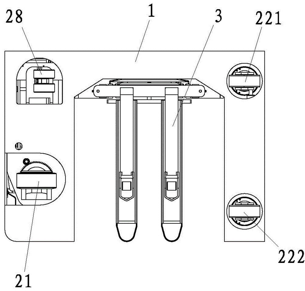
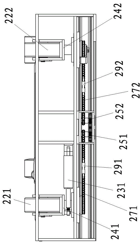
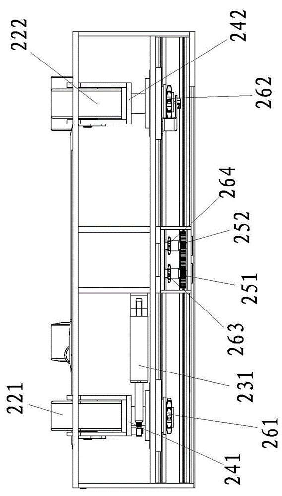
[0029] Embodiment 1: as Figure 1-3 As shown, a running mechanism of a stacker truck includes a vehicle body 1 and a road wheel assembly disposed on the body 1 . The road wheel assembly includes a driving wheel 21 and a first driven wheel 221 and a second driven wheel 222 that are interlocked with each other.

[0030] The body 1 is rotatably connected with a first mount 241 for mounting the first driven wheel 221 ; and the body 1 is rotatably connected with a second mount 242 for mounting the second driven wheel 222 .

[0031] The vehicle body 1 is rotatably connected with a first gear 251 and a second gear 252 meshing with each other.

[0032] The first mounting base 241 is coaxially and radially fixedly connected with a first sprocket 261 ; the second mounting base 242 is coaxially and radially fixedly connecting with a second sprocket 262 .

[0033] The first gear 251 is coaxially and radially fixedly connected with a third sprocket 263 ; the second gear 252 is coaxially a...

Embodiment 2

[0040] Embodiment 2: The difference with Embodiment 1 is that, as Figure 4 As shown, the driving device is an electric steering device 232 ; and the output shaft of the electric steering device 232 is directly connected to the first gear 251 , and directly drives the first gear 251 to rotate.

Embodiment 3

[0041] Embodiment 3: The difference from Embodiment 1 is that the driving device is an electric steering device 232 ; and the output shaft of the electric steering device 232 is directly connected to the second gear 252 , and the second gear 252 is directly driven to rotate.


PUM


Abstract

The invention relates to piling car technologies, in particular to a walking mechanism of a piling car. According to the technical scheme, the walking mechanism of the piling car comprises a car body and a walking wheel assembly arranged on the car body, the walking wheel assembly comprises a driving wheel, a first driven wheel and a second driven wheel, the central axis of the first driven wheel and the central axis of the second driven wheel can relatively rotate in the opposite directions, and the rotating angle ratio is 1:-1. The walking mechanism can achieve longitudinal walking, in-situ rotation and transverse translation.

Description

technical field [0001] The invention relates to stacker truck technology, in particular to a running mechanism of a stacker truck. Background technique [0002] In the prior art, the walking mechanism of relevant industrial vehicles, such as a universal driving forklift disclosed in the invention patent application with the publication number CN1789105A, includes a vehicle frame, the vehicle frame is connected with the front axle, and the front axle is connected with the mast. Left and right front wheels are arranged at both ends of the front axle, and the left and right synchronous gear sets are fixed on the front axle. The rear wheels are arranged at the rear end of the frame, and the rear steering wheels are arranged on the rear wheels. The left front wheel steering gear is fixed on the left front wheel, and the right front wheel steering gear is fixed on the right front wheel. The right front wheel steering gear is connected with the lower gear of the right synchronous g...

Claims


Application Information

Patent Timeline
Patent Type & Authority Applications(China)
IPC IPC(8): B62D15/00B62D5/00B62D3/02
CPCB62D15/00B62D3/02
Inventor 方勇周学军彭飞宇吴鑫李斌斌
Owner NOBLEELEVATOR INTELLIGENT EQUIP CO LTD
Learn More