A fully automatic core box replacement mechanism for a core making machine

A core making machine, fully automatic technology, which is applied to conveyor objects, transportation and packaging, etc., can solve the problems of equipment automation requirements affecting core removal efficiency, difficulty in hoisting and core removal automation, waste of operation time, etc. The effect of productivity and workshop automation, flexible production methods, and improved efficiency

Active Publication Date: 2016-08-31
SUZHOU MINGZHI TECH
View PDF8 Cites 0 Cited by
  • Summary
  • Abstract
  • Description
  • Claims
  • Application Information

AI Technical Summary

Problems solved by technology

[0002] The existing core-making machines are generally equipped with a core-making station and a coring station. The core box is moved to the coring station or the core is moved to the coring station by the core trolley. Since both hoisting and coring are at the coring station, it is difficult to realize the automation of hoisting and coring. When hoisting core boxes at the coring station, the hoisting tools and core boxes need to occupy the space of the coring station, which will have an impact on the arrangement of automatic coring devices (such as coring robots, coring manipulators) and roller lines. If multiple sets of core boxes need to be replaced in the actual production process, it is necessary to manually remove the original core boxes and then manually lift the other core boxes. Therefore, before core making, the core boxes are generally lifted to the On the core box trolley of the core making machine, then the core box enters the interior of the core making machine with the core box trolley to realize manual / automatic installation and fixing. If the used core box needs to be replaced, the original installed core box needs to be moved to the core taking place Then hoist it away from the core box trolley, and then hoist other core boxes to the core box trolley of the core making machine for installation. The manual core removal method will affect the efficiency of core removal and equipment automation requirements. Hoisting the core box wastes operating time and affects production efficiency

Method used


Image

  • A fully automatic core box replacement mechanism for a core making machine
  • A fully automatic core box replacement mechanism for a core making machine
  • A fully automatic core box replacement mechanism for a core making machine

Examples


Embodiment 1

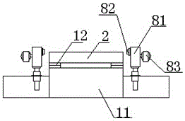
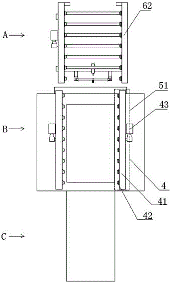
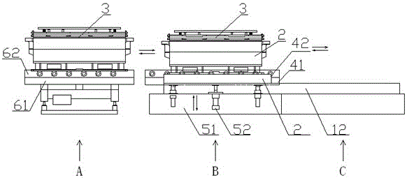
[0029] see Figure 1-Figure 3, as shown in the legend therein, is a fully automatic core box replacement mechanism for a lower core core making machine. The core making machine has a lifting station A, a core making station B and a coring station C arranged in sequence along the longitudinal direction, The above-mentioned core making machine includes a first conveying device, a core box trolley 2 and a core box 3. The first conveying device is arranged as a guide rail 12 located on the first base 11, and its two ends are respectively connected to the core making station B and the coring worker. Corresponding to the position C, the core box trolley 2 is connected to the guide rail 12 through the driving movement of the core box trolley driving device and reciprocates between the core making station B and the coring station C. The above-mentioned fully automatic core box replacement mechanism includes the first Two conveying devices, a lifting drive device, and a third conveying...

Embodiment 2

[0033] see Figure 4 and Figure 5 , as shown in the legend, the rest is the same as the first embodiment, the difference is that the core making machine is also provided with a switching hoisting station IA1 and a switching hoisting station IIA2 located on the lateral sides of the hoisting station A, The core making machine also includes a station switching conveying device. The station switching conveying device is set as a roller table 72 located on the traversing base 71. The roller table 72 passes through the switching hoisting station IA1, the hoisting station A and the switching hoisting station in sequence. IIA2, the above-mentioned third conveying device includes the third conveying device I63 and the third conveying device II64 arranged on the above-mentioned station switching conveying device, when the above-mentioned station switching conveying device is in the first working state, the third conveying device I63 and the hoisting The position of station A correspon...

Embodiment 3

[0037] see Figure 6 and Figure 7 , as shown in the legend therein, the rest are the same as the second embodiment, the difference is that the core making machine is a lower core making machine, and the lower core making machine is also provided with a and the transition station D between the core making station B, the above-mentioned automatic core box replacement mechanism also includes a transition conveying device, and the above-mentioned transition conveying device is arranged between the second conveying device and the third conveying device, and is arranged to be located at the first The roller table 92 on the four bases 91, when the above-mentioned lifting drive device is in the first working state, the conveying support surface of the second conveying device, the conveying supporting surface of the transition conveying device and the end of the conveying supporting surface of the third conveying device are connected flat, The core box 3 is located on the conveying s...


PUM


Abstract

The invention discloses a full-automatic core box replacing mechanism of a core making machine. A hanging station, a core making station and a core taking station are longitudinally and sequentially arranged on the core making machine. The full-automatic core box replacing mechanism comprises a second conveying device, a lifting drive device and a third conveying device. The second conveying device comprises two conveying roller sets which are arranged on the two transverse sides of the core making station in parallel. The lifting drive device drives and are connected with the two conveying roller sets in the vertical direction. The third conveying device corresponds to the hanging station. The end of the conveying supporting face of the second conveying device and the end of the conveying supporting face of the third conveying device are flat connected or the conveying supporting faces of the two conveying roller sets are lower than the core box supporting face of a core box trolley. According to the technical scheme, the core taking station and the hanging station are separately arranged, an automatic core taking device or a roller line can be arranged at the core taking station, an automatic hanging and switching device can be arranged at the hanging station as well, and the requirement for the automation of the device is met.

Description

technical field [0001] The invention relates to a core box replacement mechanism, in particular to a fully automatic core box replacement mechanism for a core making machine. Background technique [0002] The existing core-making machines are generally equipped with a core-making station and a coring station. The core box is moved to the coring station or the core is moved to the coring station by the core trolley. Since both hoisting and coring are at the coring station, it is difficult to realize the automation of hoisting and coring. When hoisting core boxes at the coring station, the hoisting tools and core boxes need to occupy the space of the coring station, which will have an impact on the arrangement of automatic coring devices (such as coring robots, coring manipulators) and roller lines. If multiple sets of core boxes need to be replaced in the actual production process, it is necessary to manually remove the original core boxes and then manually lift the other co...

Claims


Application Information

Patent Timeline
Patent Type & Authority Patents(China)
IPC IPC(8): B65G47/52
Inventor 王鼎铭顾海兵徐磊磊王直良
Owner SUZHOU MINGZHI TECH
Why Eureka
Try Eureka