Tension adjusting device for film covering roller of die cutting machine

A tension adjustment device and die-cutting machine technology, which are applied in the directions of transportation and packaging, winding strips, and thin material processing, can solve the problems of unadjustable tension, setting of laminating rollers, and breaking of material strips, and achieve structural Simple, flexible and convenient operation

Inactive Publication Date: 2015-03-25
GUANGDONG FXD INTELLIGENT EQUIP CO LTD
View PDF12 Cites 8 Cited by
  • Summary
  • Abstract
  • Description
  • Claims
  • Application Information

AI Technical Summary

Problems solved by technology

[0002] At present, die-cutting machines have film-coated rollers for conveying material belts. During the transmission process, the tension degree of material belts in different sections will be different, and the thickness of different material belts will also be different. These Both will affect the conveying performance of the coated roller
However, if figure 1 As shown, the upper roller 10 and the lower roller 12 of the existing film-coated roller are all installed on the frame 30 by corresponding roller shafts 20, 22, but after the assembly is completed, the upper roller 10 and the lower roller 12 The distance between the upper roller 10 and the lower roller 12 can only be adjusted to match the thickness of the strip by means of the spacing adjustment device 40 installed on the frame 30 at both ends of the upper roller 10, but the upper roller 10 or the tension of the lower roller 12 cannot be adjusted, therefore, it is impossible to set different tensions for the film-coated roller according to the actual needs of the production process, which has an adverse effect on the transmission of the material belt, and may not be able to effectively convey the material belt , in severe cases, it may even break the tape

Method used


Image

  • Tension adjusting device for film covering roller of die cutting machine
  • Tension adjusting device for film covering roller of die cutting machine

Examples


Embodiment Construction

[0014] It should be noted that, in the case of no conflict, the embodiments in the present application and the features in the embodiments can be combined with each other. The present invention will be further described in detail below in conjunction with the drawings and specific embodiments.

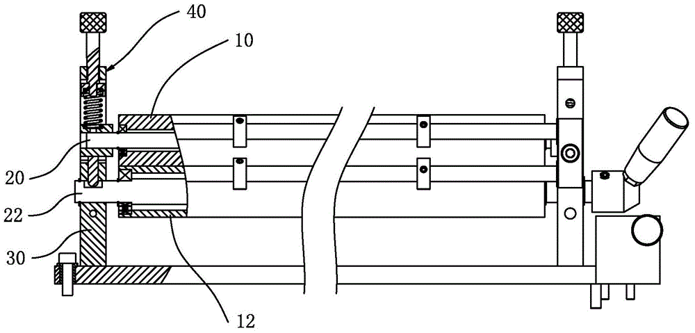
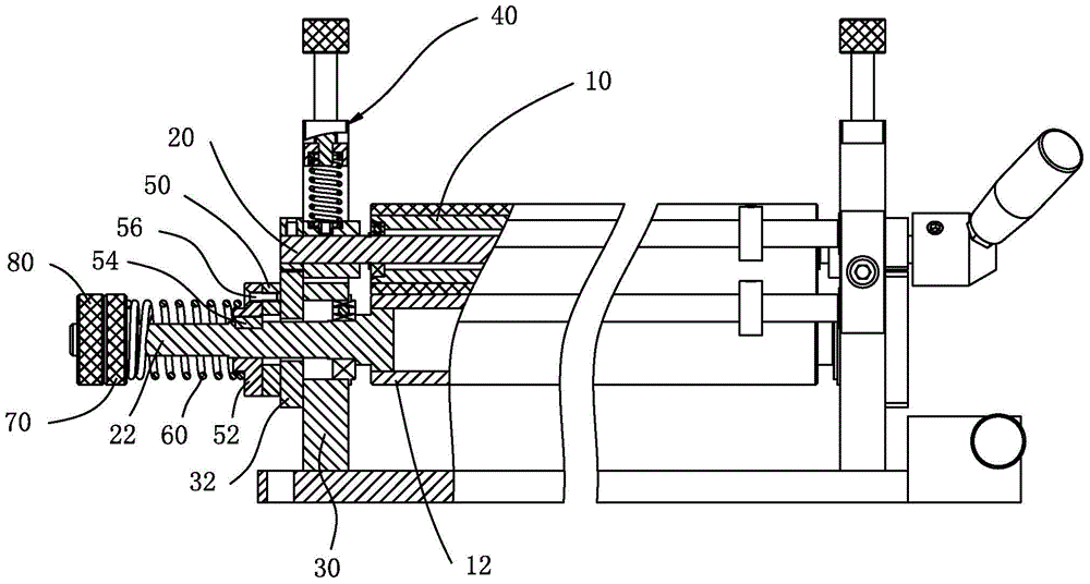
[0015] like figure 2 As shown, the laminating roller of a die-cutting machine generally includes an upper roller 10, a lower roller 12, and an upper roller shaft 20 and a lower roller for assembling the upper roller 10 and the lower roller 12 to the frame 30 respectively. The shaft 22 is also provided with a distance adjusting device 40 for adjusting the distance between the upper roller 10 and the lower roller 12 on the frame 30 at both ends of the upper roller 10 . And the present invention provides a kind of die-cutting machine laminating roller tension adjustment device, it comprises the lower roller shaft 22 that is used for the lower roller 12 in the laminating roller of cross-c...


PUM


Abstract

The invention provides a tension adjusting device for a film covering roller of a die cutting machine. The tension adjusting device comprises a lower roller shaft used for installing a lower roller in the film covering roller of the die cutting machine to a machine frame in a pivoted mode. One end of the lower roller shaft extends to the outer side of the machine frame. The part, extending out of the outer side of the machine frame, of the lower roller shaft is sleeved with a friction block. The friction block can move relative to the lower roller shaft in the axial direction and is fixed relative to the lower roller shaft in the circumferential direction. A spring and an adjusting handle are arranged on the outer side of the friction block. The spring is arranged on the lower roller shaft in a sleeving mode and used for compressing the friction block onto the machine frame. The adjusting handle is in screw fit with the tail end of the lower roller shaft so that the elastic pressure of the spring on the friction block can be kept. The tension adjusting device at least has the advantages that the spring keeps compressing the friction block so that the friction block can tightly abut against the outer side face of the machine frame, the compression force of the spring is adjusted through the adjusting handle, and therefore friction force between the friction block and the outer side face of the machine frame can be increased or decreased, and then the tension of the lower roller is changed correspondingly so as to adapt to actual demands. The tension adjusting device is simple in structure and flexible and convenient to operate.

Description

technical field [0001] The invention relates to the technical field of die-cutting machines, in particular to a device for adjusting the tension of a coating roller of a die-cutting machine. Background technique [0002] At present, die-cutting machines have film-coated rollers for conveying material belts. During the transmission process, the tension degree of material belts in different sections will be different, and the thickness of different material belts will also be different. These Both will affect the transfer performance of the coated roller. However, if figure 1 As shown, the upper roller 10 and the lower roller 12 of the existing film-coated roller are all installed on the frame 30 by corresponding roller shafts 20, 22, but after the assembly is completed, the upper roller 10 and the lower roller 12 The distance between the upper roller 10 and the lower roller 12 can only be adjusted to match the thickness of the strip by means of the spacing adjustment device...

Claims


Application Information

Patent Timeline
IPC IPC(8): B65H23/188
CPCB65H23/1888B65H2301/11
Inventor 侯立新
Owner GUANGDONG FXD INTELLIGENT EQUIP CO LTD
Why Eureka
Try Eureka